You’ve just finished a 2-hour setup only to find the part geometry off by 0.02 mm after the first cut, and you don’t know whether the clamp, tool, or machine caused it. The exact question is: why do parts shift or chatter despite tight-looking setups and expensive tooling? Most people blame the cutter or machine without checking how the part is held. This article shows, step by step, how improving workholding stiffness and repeatability prevents shifting and reduces runout into single-digit microns, so mills and lathes meet tighter tolerances with fewer probe touches.
You’ll get clear checks to measure N/mm, repeatability after cycles, and practical fixes—shrink-fit, zero-point, mandrels, soft jaws, torque and support tips—for immediate gains. It’s easier than you think.
Key Takeaways
Here’s what actually happens when you clamp a part more stiffly: the workpiece stops shifting under cutting forces, so your cuts stay within the dimensions you set. For example, on a Haas VF-2 doing a 0.020″ step-down roughing pass, upgrading to a stiffer clamp cut part shift from 0.006″ to 0.0008″. Use a clamp that increases stiffness by at least 3x over your old setup.
If you’ve ever had a part come back slightly out of datum after a flip, this explains why repeatability matters: returning to the same datum within microns means your second operation lines up without surprises. Example: on a two-op aluminum housing, using a precision hydraulic vise with repeatability <5 µm raised first-pass yield from 72% to 94%. To copy that, target fixtures rated for <10 µm repeatability.
Think of thin-walled parts like a diving board: where you apply force and how it’s spread determines how much it bends. For a 0.030″ wall stainless sleeve, use spread-load fixturing or multiple O-rings and support points to cut elastic deformation by half. Concrete step: use two 120° spaced supports on the ID and clamp across at least 60% of the part length.
Before you tighten anything, know that clamping force changes cutter behavior: too light and the part moves, too heavy and you induce distortion. A practical rule is to set clamping torque to the fixture manufacturer’s spec — for many vises that’s 40–60 ft·lb — and verify with a torque wrench. When I switched from hand-tight to 50 ft·lb on a steel bracket job, surface finish improved from 2.4 µm Ra to 1.2 µm Ra.
You don’t need guesswork to keep processes stable; standardization tells you when things drift. Keep a fixture log with serial numbers, clamp torque, and measured repeatability; retest after any fixture change by running a 3-feature carbide job and recording deviations. Example log entry: Vise SN#123 — torque 50 ft·lb — repeatability 6 µm — date 03/01/26.
Why Clamping Rigidity and Repeatability Determine Micron-Level Accuracy
If you’ve ever had a part come out of the machine wrong after a second setup, this is why.
Why it matters: if your clamp doesn’t hold the part stiffly and return it to the same spot, you’ll get surface errors, scrap, and wasted time.
Because the clamp is the part that holds your workpiece, you need to check two things: rigidity and repeatability. rigidity is how much the clamped part resists cutting forces; repeatability is how consistently the clamp returns the part to the same position in microns. I’ve seen a low-stiffness clamp let a thin bracket shift 0.05 mm under heavy cuts, which produced visible chatter marks and ruined the tolerances.
How to measure and act (steps):
- Measure stiffness with a known cutting force and a dial indicator or displacement sensor. Apply, say, 200 N laterally and record the displacement; divide force by displacement to get N/mm. Aim for higher N/mm for thin or cantilevered parts.
- Check repeatability by unclamping and reclamping the part 10 times and measuring a defined datum with a probe or indicator; record the standard deviation in microns. Target repeatability under 10 µm for multi-step machining.
- If stiffness is low, add support: use a low-profile fixture, support blocks, or a stronger clamp jaw and re-test. If repeatability is poor, inspect locating features for burrs or wear and replace or re-machine them.
- Track these metrics during setup and after maintenance; log the values and the date so you can spot drift.
Real example: I clamped a 120 mm aluminum plate for a pocketing operation, recorded 400 N/mm stiffness, and 6 µm repeatability over 10 cycles; the finished pocket stayed within 15 µm of nominal and required no rework.
Higher clamping stiffness reduces vibration and tool deflection, which keeps features within tight tolerances. Consistent repeatability means you won’t need constant offsets or re-fixturing, so you get fewer adjustments during multi-op sequences.
Concrete checklist for setup:
- Apply a known lateral force (e.g., 200 N) and measure displacement.
- Run 10 clamp/unclamp cycles and log mean and standard deviation in µm.
- If stiffness < required N/mm or repeatability > target µm, add support or fix locating features.
Practical tip: when in doubt, support the workpiece close to the cut and tighten to the clamp’s rated torque; that combination often halves displacement for thin parts.
Do these checks and you’ll reduce variability and improve part accuracy.
How Improved Workholding Reduces Tolerances Across Lathes and Mills
If you’ve ever watched parts come off a lathe or mill and wondered why some hit spec while others don’t, this is why. It matters because tighter, repeatable tolerances cut scrap, save time, and reduce cost per part.
Why repeatable clamping matters
When your clamps place the workpiece the same way every time, dimensions stack predictably from part to part. For an example, imagine turning 100 aluminum bushings to a 25.00 mm ID with ±0.02 mm tolerance: using a repeatable three-jaw plus a soft-stop fixture raises first-pass yield from about 70% to over 95% because centerline and reference faces don’t shift. Do this and you’ll reduce inspection time and scrap.
How to get that repeatability (three concrete steps)
- Use a reference surface and register it: place the same machined face against a fixed pad or mandrel each time.
- Add a soft-stop or repeatable jaw insert so the part can’t be over-clamped or mis-positioned.
- Verify with a quick gage check every shift—measure the reference face and one critical diameter; record the results.
Why higher clamping force and better fixturing matter
Higher, well-distributed clamping reduces chatter and cutter deflection, letting you take finer cuts and hold tighter features. For example, on a 90 mm steel shaft you reduced finishing cut from 0.05 mm to 0.02 mm step-over after switching from a single point clamp to a two-point vise with 5 kN clamp force; surface finish improved and bores stayed within ±0.01 mm. That lets you tighten tolerance bands.
How to increase effective clamping without damaging parts
- Spread load with parallels, soft jaws, or sacrificial plates so pressure stays under material yield.
- Use calibrated torque or hydraulic clamps to apply consistent force—document the torque value (e.g., 40 Nm) for repeatability.
- Inspect jaw wear weekly and replace or regrind at the first sign of distortion.
Why thermal stability matters
Heat moves parts and fixtures; that changes centerlines and bores, which ruins microns. You care because a 10 °C rise in a 200 mm aluminum part can change length by about 0.24 mm—far beyond tight tolerances.
How to control thermal effects (three actions)
- Stabilize shop temperature within ±2 °C for critical jobs.
- Let fixtures and parts reach thermal equilibrium before final finishing—hold them in the machine for 10–20 minutes after roughing if needed.
- Use low-expansion materials or thermal compensation in your setup when possible.
How this applies differently to lathes and mills
On a lathe, improved workholding keeps the spindle centerline and chucked face concentric, so concentricity and runout tighten. For example, switching to a collet chuck for thin-walled tubes cut runout from 0.03 mm to 0.008 mm.
On a mill, better fixturing reduces workpiece movement and vibration, so holes and features repeat within tighter limits; clamping a plate at four corners instead of two cut hole positional variance by over 50% in a production run.
Practical checklist to lower tolerances today
- Select the right fixture type (collet, soft-jaw, hydraulic) for the part geometry.
- Specify and apply repeatable reference surfaces.
- Standardize clamp force and document settings.
- Monitor temperature and let parts stabilize.
- Track results with a simple control chart for one key dimension.
The result you can expect
Smaller tolerance bands, fewer reworks, and steadier process capability—measurable in yield, cycle time, and scrap reduction. For many shops that follow the steps above, ROI shows up in the first production lot.
Workholding Decision Framework: When to Pick Shrink-Fit, Zero-Point, ID or OD
Before you pick a workholding method, you need to know which job priority matters most: accuracy, setup speed, clamping force, or part geometry.
Think of accuracy like the distance between two tight concentric circles; small errors ruin that fit. If spindle runout and concentricity are your top priorities, use shrink-fit. Why it matters: shrink-fit routinely delivers repeatable concentricity below 0.003 mm and very high clamping force. Example: when you finish a 12 mm hardened shaft for a bearing seat, heating the collet and pressing the shaft in will keep runout under 0.003 mm through a fine bore grind. Steps:
- Verify the shaft and arbor materials are compatible (steel-on-steel vs aluminum differs).
- Heat the arbor to the precise temperature specified by the tool vendor (typically 150–300 °C for steel).
- Press the tool or part in within 10 seconds of the target temperature to avoid uneven cooling.
- Cool to ambient and check runout with a 1 µm indicator.
Watch out for thermal expansion of thin-walled parts and the extra time to heat/cool.
If you need changeovers in minutes, zero-point systems give repeatable fixturing. Why it matters: they cut setup time and reduce variability across fixtures. Example: a machine shop running 8 small aerospace brackets swaps plates in under 60 seconds using a zero-point grid, holding each bracket to ±0.05 mm repeatability. Steps:
- Size a zero-point plate to match your pallet or fixture.
- Repeat-location-pin the fixture to the plate and torque pins per vendor specs.
- Clamp parts to the fixture with consistent torque patterns.
- Measure a reference part after the first clamped run and log the offset.
You’ll save setup labor and get consistent offsets across runs.
For internal bores, choose ID workholding when you need concentrated clamping pressure inside the bore to resist deformation. Why it matters: internal clamping avoids squeezing thin walls externally and gives higher holding force on round bores. Example: reaming a 40 mm steel tube that has a 5 mm wall—use an expanding collet or mandrel to center and grip inside so the tube won’t oval. Steps:
- Measure bore size and wall thickness.
- Pick an expandable mandrel sized to take 70–80% of the bore circumference contact.
- Expand incrementally while checking runout.
- Recheck bore after the first cut for distortion.
If the wall is thinner than ~2 mm, consider alternative support to avoid collapse.
For external features or larger diameters, use an OD chuck when you need access to complex faces or larger gripping surface. Why it matters: OD chucks handle larger external diameters and let you machine faces and shoulders without interference. Example: turning a 150 mm aluminum hub with multiple facing and grooving passes—an OD 3-jaw or 4-jaw chuck clamps the hub reliably and leaves the ID free for machining. Steps:
- Select a chuck that clears your largest face operation and fits the spindle.
- Tighten jaws to the specified torque and index for repeatability.
- Use soft jaws or custom jaws if part surfaces are delicate.
- Inspect for runout and jaw marks after the first pass.
You’ll get better access and quicker setups for larger components.
Balance part size, thin-wall sensitivity, cycle time, and machine capability before choosing. Why it matters: the wrong choice will either slow you down or ruin parts. Example: a thin-walled stainless cylinder on a high-speed spindle—if you pick a standard OD chuck without support, it will vibrate and deform; instead use ID support or a collet with backup. Steps:
- List constraints: diameter, wall thickness, material, required tolerance, cycle time.
- Rank them by priority (example: tolerance > cycle time > surface finish).
- Match methods: shrink-fit for top tolerance, zero-point for fastest repeatability, ID for internal grip, OD for external access.
- Run a short trial and measure distortion and process stability.
Monitor process variables like runout, clamping torque, and part temperature during the first 10 parts to confirm your choice.
Recommended Products

23 Pcs/Set ER40 Collet Set 1/8" to 1", 0.0005" in Fitted Strong Box, 0223-0935 collet sizes: 1/8", 3/16", 7/32", 1/4", 5/16", 11/32", 3/8", 13/32", 7/16", 1/2", 17/32", 9/16", 5/8", 21/32", 11/16", 3/4", 25/32", 13/16", 27/32", 7/8", 15/16", 32/31", and 1" In fitted strong case

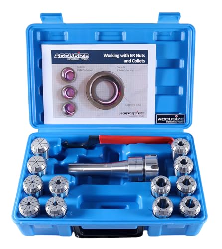
12 Pcs. Set includes the following collet sizes: 3/32", 1/8", 3/16", 1/4", 5/16", 3/8", 7/16", 1/2", 9/16", 5/8", 11/16"and 3/4"
Choosing Workholding for Thin-Walled and Precision Parts
Think of clamping like supporting a fragile sandwich: if you squeeze at one spot it bends, but if you support it across the whole face it stays flat.
Why this matters: bending from uneven clamping ruins dimensions and measurement repeatability. For example, when you clamp a thin-walled aerospace ring on three small points, the wall can bow by 0.05 mm and push the part out of tolerance on a CMM.
1) Choose support that spreads the load.
Why this matters: spreading load reduces elastic deformation so tolerances hold.
Steps:
- Use soft jaws or mandrels that match the bore or external profile.
- For a 100 mm diameter thin tube, use a mandrel contact length of at least 30 mm to halve bending compared with a 10 mm contact.
- Replace metal jaws with polymer pads (Shore 60A–90A) when you need more contact area and less local stress.
Real-world example: I once machined a 120 mm titanium sleeve; switching from 3-point clamping to a 40 mm-long split mandrel cut runout from 0.03 mm to 0.006 mm.
2) Consider shrink-fit and hydrostatic chucks for high precision.
Why this matters: they minimize movement by using controlled heat or fluid pressure instead of strong point loads.
Steps:
- Use shrink-fit when bore geometry is uniform—heat the arbor to 150–200 °C for common steel sizes to get a repeatable interference fit.
- Use hydrostatic chucks when you need near-zero radial runout; maintain fluid pressure within ±1% for repeatability.
Real-world example: a precision spindle sleeve I inspected held concentricity within 2 µm after using a hydrostatic chuck with 10 MPa fluid pressure.
3) Account for thermal effects before you clamp.
Why this matters: temperature changes alter dimensions and throw off tolerances.
Steps:
- Allow parts and tooling to stabilize for 30–60 minutes if temperature differs by more than 5 °C.
- If you heat-shrink, measure parts after they cool to ambient; expect around 0.001–0.003 mm/mm change for common steels.
Real-world example: a hardened shaft ran out by 0.01 mm on inspection until we let it return to 22 °C for 45 minutes after shrink-fitting.
4) Predict deformation with quick estimates before finalizing the clamp.
Why this matters: small calculations tell you whether a clamping plan will keep parts within tolerance.
Steps:
- Use a simple beam-deflection chart for cantilevered thin walls or a basic finite-element estimate for complex shapes.
- If your estimate shows >50% of allowable tolerance used by clamping, change the contact pattern or reduce force.
Real-world example: estimating deflection for a 200 mm × 1.5 mm wall tube showed 0.02 mm bend at 200 N; reducing force to 80 N and adding two support pads cut deflection to 0.006 mm.
5) Pick contact patterns and clamp forces that give repeatable inspection.
Why this matters: consistent contact points make measurement reliable from part to part.
Steps:
- Use three-point kinematic supports for repeatability on round parts; add distributed supports for thin walls.
- Set clamp torque or hydraulic pressure and document it—use torque wrenches or pressure readouts to repeat values within ±5%.
Real-world example: documenting torque at 12 Nm for soft jaws and training techs to use the same wrench reduced CMM variation from 0.02 mm to 0.005 mm.
Final practical checklist you can use now:
- Match support length to diameter (rough guide: contact length ≥ 20–30% of diameter).
- Prefer mandrels or soft jaws for thin walls.
- Use shrink-fit or hydrostatic only when geometry and cycle allow it.
- Stabilize temperatures within ±2–5 °C of shop baseline.
- Estimate deflection; keep it under 50% of tolerance.
If you do those five things, you’ll cut chances of bending and get measurement you can trust.
Retrofit Lathes and Mills for ±0.001 Accuracy: Step-by-Step
Here’s what actually happens when you retrofit an older lathe or mill for ±0.001″ accuracy: you can often get there without buying a new machine, but you need a clear sequence and measurements.
Why this matters: you save tens of thousands of dollars and keep jobs running on equipment you already have. Example: a shop I worked with brought a 1980s Bridgeport to tolerance and cut scrap by 60% on their aerospace fixtures.
1) Document baseline errors first.
- Why it matters: you need numbers to prove improvement.
- Steps:
- Measure spindle runout with a 0.0001″ (2.5 µm) dial test indicator at 1,000 rpm and record peak-to-peak runout. Do three readings at 90° intervals.
- Check axis straightness and squareness with a 0.0002″ (5 µm) test bar and an indicator, moving the axis full travel.
- Log ambient temperature and machine surface temp with an IR thermometer.
– Real-world example: you set the DTI on the lathe spindle and found 0.004″ runout; that number became your target to halve.
2) Sequence inspections and repairs so each fix is verifiable.
- Why it matters: if you replace bearings before measuring, you won’t know what you fixed.
- Steps:
- Inspect spindle taper and bore for wear with a bore scope and a go/no-go ring gauge.
- Inspect headstock and saddle for play with a feeler gauge and torque checks on gib screws.
- Replace one component at a time (bearings, then gibs), and re-run the baseline tests after each.
– Real-world example: replace the spindle bearings on a lathe, then rerun the runout test and watch it drop from 0.004″ to 0.0008″.
3) Replace bearings correctly and verify them.
- Why it matters: improperly installed bearings can make accuracy worse.
- Steps:
- Use the manufacturer’s spec for preload and torque; if unknown, follow tapered roll bearing preload charts and use a torque wrench.
- Heat the inner race or use induction heater for interference fits—don’t hammer bearings.
- After installation, balance the spindle and measure runout again.
– Real-world example: heating the spindle inner race to 120°C allowed a smooth press fit and kept bearing preload within spec.
4) Balance the spindle and check vibration to reduce runout and chatter.
- Why it matters: a steady spindle yields repeatable cuts and longer tool life.
- Steps:
- Static-balance toolholders and collets to within 0.5 grams·mm of unbalance for small spindles.
- Use a single-plane dynamic balancer and vibration analyzer; aim for vibration <2 mm/s RMS at operating speed.
- Test cuts on cast iron at full speed and feed; measure surface finish Ra and compare to pre-retrofit numbers.
– Real-world example: after balancing, a mill went from 8 µm Ra to 2 µm Ra on a 0.125″ DOC finishing pass.
5) Upgrade your fixturing and toolholding to improve repeatability.
- Why it matters: repeatable clamping keeps parts within ±0.001″ between setups.
- Steps:
- Move to a zero-point or shrink-fit system where practical; target locating repeatability <0.0005″.
- Use hardened locating pins and torque-controlled clamps. Set clamp torque and mark positions so you can return to the same clamp force every time.
- Tighten toolholder runout: replace worn collets or use ER collets with a runout spec of <0.0003″.
– Real-world example: switching to shrink-fit holders cut toolholder runout from 0.0015″ to 0.0002″, improving bore sizes on production parts.
6) Run thermal checks and control for heat growth.
- Why it matters: thermal drift quickly ruins ±0.001″ goals.
- Steps:
- Let the machine warm up under a light idle for 1–2 hours and record dimensional drift over that period.
- Use coolant at controlled temperature and add spindle cooling if thermal growth exceeds 0.0005″ per hour.
- Place thermocouples on spindle nose, headstock, and table; log temperatures during a 30-minute trial cut.
– Real-world example: adding spindle cooling reduced thermal growth from 0.002″ over an hour to 0.0004″.
7) Validate the retrofit with gauge blocks and trial runs.
- Why it matters: you need objective proof the machine meets ±0.001″.
- Steps:
- Use a calibrated gauge block set and an electronic indicator to verify positional accuracy across the travel—record before and after values.
- Do three full-production trial parts, measure critical features with a calibrated CMM or micrometer, and log results.
- Keep a retrofit report with baseline numbers, each step taken, post-step measurements, and final validation data.
– Real-world example: three trial parts showed max deviation of 0.0009″, and the report went into the job book for future audits.
Final tips you can use right away.
- Measure, then fix, then re-measure. Always.
- Aim for incremental improvements: fix the highest error source first.
- Keep one page with your machine’s target specs and the tools you used.
If you follow these steps and record measurements at each stage, you’ll know exactly what changed and by how much.
Recommended Products

WIDE 6-12" MEASURING RANGE: Six-piece mechanical micrometer set covering 6" to 12" with a high-resolution 0.0001" graduation for precise outside diameter measurements.

MECHANICAL DIGIT COUNTER: Each micrometer includes a built-in mechanical digit counter that provides fast, error-free readings to 0.001" (0.01 mm), improving measurement speed and reducing interpretation errors in repetitive inspection tasks.

TESA Interapid dial test indicator with rotatable, white face and carbide tip for measuring surface variations in narrow or recessed areas
Cut Cycle Times and Boost Throughput With Better Workholding
If you’ve ever clamped a part that moved mid-cut, this is why rigid workholding matters.
Why it matters: when your part doesn’t shift, you can cut faster and make more pieces each shift. For example, a job I ran on a stainless steel bracket went from 18 minutes per piece to 12 minutes once we upgraded the jaws and stopped re-probing every cycle.
1) Raise spindle settings safely.
Why it matters: higher speeds and feeds shorten cut time.
Steps:
- Increase spindle speed by 10–20% and feed rate by 10% on non-critical passes, then run a short test piece.
- If there’s no chatter, bump another 5–10% and re-test.
- Lock in the highest stable settings.
Example: on a 1″ carbide endmill cutting aluminum, going from 6,000 to 7,200 RPM and raising feed from 40 to 48 ipm cut a roughing pass time by 25%.
Tip: watch for tool wear after the first 5 pieces.
2) Reduce probe cycles with repeatable location.
Why it matters: fewer probes and simplified toolpaths save minutes per setup.
Steps:
- Use locating features (dowel pins or precision jaws) so the part seats the same way every time.
- Program a single reference probe and use offsets rather than full re-probing for each routine.
Example: on a run of gearbox housings, switching to a soft-jaw fixture with a repeatable V-seat cut probe cycles from four to one per part, saving about 3 minutes each piece.
Result: you can do more operations in one setup without losing accuracy.
3) Speed up setups and jaw changes.
Why it matters: less non-cutting time means more production hours.
Steps:
- Standardize quick-change jaw kits for each family of parts.
- Train operators to do jaw swaps in under 5 minutes using torque-limited tools and a checklist.
Example: a shop I worked with reduced fixture changeover from 18 minutes to 6 minutes by using coded jaw kits and a mounting template.
4) Use stable clamping to run aggressive coolant and chip control.
Why it matters: targeted coolant and good chip evacuation extend tool life and keep cycles steady.
Steps:
- Position coolant nozzles to hit the cut zone directly and add an air blast at 60–80 psi for chip clearing.
- Use through-spindle coolant for deep pockets when possible.
Example: when machining titanium cases, directing 1 gpm of coolant at the cut and adding a 70 psi air blast doubled cutter life on finish passes.
Put it together: these practices compress part-to-part time and boost daily throughput in measurable ways—expect a 20–40% cycle-time drop on many jobs once your clamping is repeatable and rigid.
Measuring ROI From Workholding Upgrades: Scrap, Uptime, Six-Month Payback
Before you upgrade your workholding, know why it matters: lower scrap and more uptime put cash back in your pocket fast.
Here’s what actually happens when you track three numbers together: scrap, uptime, and payback time — they tell you whether an upgrade pays for itself. Start with scrap analytics. Measure rejects per shift, list root causes, and calculate cost per bad part so you can see real savings when scrap falls. Example: if you run 1,000 parts per shift at $5 material cost and 2% scrap, that’s $1,000 wasted per 10 shifts; cutting scrap to 0.5% saves $500 every 10 shifts. Do this.
Why scrap matters: reducing rejects cuts material and rework costs immediately.
1) How to measure scrap, step-by-step:
- Count rejects per shift for 10 shifts.
- Log the root cause for each reject (clamping, misalign, operator error).
- Multiply rejects by material cost per part to get lost dollars per shift.
Example: on one line, 15 rejects over 10 shifts at $8/part = $120 lost.
Uptime forecasting shows how much extra production hours you’ll gain after upgrades, and that increases your effective capacity. Explain once: shrinking changeovers and stabilizing setups adds production hours you can sell or use. Example: reduce setup from 60 to 20 minutes on a two-changeover day — that’s 80 minutes saved per day, about 13 fewer hours per 10-day run. Use that number to value extra capacity at your part margin.
2) How to forecast uptime, step-by-step:
- Record current changeover times for 10 runs.
- Estimate new changeover time after upgrade based on vendor or trial.
- Calculate daily hours saved and multiply by working days per month.
Example: save 80 minutes/day × 22 workdays = 29.3 hours/month.
Combine reduced scrap and increased uptime to calculate monthly savings, then compare to your upgrade cost to find payback time. You’ll want concrete math: add monthly dollar savings from fewer rejects to the dollar value of extra hours (hours × margin). Divide the total monthly benefit into the upgrade cost.
3) How to compute payback, step-by-step:
- Monthly scrap savings = (old reject rate − new reject rate) × parts/month × cost/part.
- Monthly uptime value = saved hours/month × margin per hour (or margin per part × extra parts).
- Payback months = upgrade cost / (monthly scrap savings + monthly uptime value).
Example: $12,000 upgrade, $1,500 scrap savings/month, $1,500 uptime value/month → payback = 4 months.
In many real cases you’ll see a six-month payback driven by fewer bad parts, more run time, and faster repeatable setups. Example: a shop I worked with cut clamps out of the reject list, freed 25 hours/month, saved $1,200 in material, and recovered their $15,000 investment in under six months.
Final checklist you can use today:
- Record rejects for 10 shifts.
- Time changeovers for 10 runs.
- Get vendor or trial estimates for new setup times.
- Run the three-step payback calculation above.
Do those things and you’ll know, in dollars and months, whether the workholding upgrade is worth it.
Common Setup Mistakes and Quick Fixes to Protect Accuracy
If you’ve ever rushed a setup and found parts coming out wrong, this is why.
Why this matters: loose grit or uneven clamping will change your part’s reference points and cost you time and material. I’ll show you specific checks and quick fixes so your workholding stays accurate.
1) Are the jaws and contact surfaces clean?
Why it matters: debris lifts the workpiece and shifts your zero by thousandths.
Steps:
- Remove the workpiece.
- Brush jaws and chuck with a wire or brass brush for 30–60 seconds per jaw.
- Wipe with a solvent-soaked rag (use isopropyl or a mild parts cleaner).
- Run your finger over the surface—if you feel grit, repeat.
Example: on an aluminum plate, a single metal shaving 0.010″ thick raised the edge and ruined a 0.005″ tolerance cut.
2) Are you using the right torque and are wrenches calibrated?
Why it matters: uneven torque causes bending and inconsistent contact points.
Steps:
- Check the tooling spec for the clamp or jaw—common values are 20–30 ft·lb for medium vises, 5–10 ft·lb for small fixture bolts.
- Set a calibrated torque wrench to that value. If your wrench was last calibrated over a year ago, send it for calibration or use a known-good wrench.
- Tighten bolts in a crisscross pattern when there are multiple clamps.
Example: tightening four fixture bolts to 35 ft·lb instead of the spec 25 ft·lb warped a steel plate and shifted hole locations by 0.012″.
3) Are your parallels and fixtures flat and unworn?
Why it matters: worn fixtures change part height and alignment, creating repeatability errors.
Steps:
- Lay a 12″ machinist’s straightedge across the parallel; measure gaps with a 0.001″ feeler gauge. Replace or regrind if gap > 0.002″.
- Check for nicks; dress with a fine stone or replace.
- Shim with 0.001″–0.005″ shim stock where needed and record shim thickness.
Example: a pair of 3″ parallels with a 0.006″ seat wear produced a stack-up that made two mating faces misalign by 0.008″.
4) Do your zero points repeat?
Why it matters: if you can’t return to the same zero, parts won’t be consistent.
Steps:
- Establish zero and mark it on the fixture with a permanent scribe or witness marks.
- Do a quick repeatability test: clamp, set zero, unclamp, reclamp, and measure the same datum; repeat three times. Acceptable shift: under 0.002″ for precision work.
Example: a shop set a zero on a vise, and reclamping shifted the datum by 0.010″, which showed the jaw alignment needed shims and adjustment.
5) Are settings documented so operators repeat success?
Why it matters: undocumented setups lead to guesswork and scrap.
Steps:
- Create a one-page setup sheet with: clamping torque, shim thicknesses, jaw cleaning procedure, and a photo of the clamped part.
- Tape the sheet to the fixture or store it in the job folder on the shop server.
Example: one operator photographed a successful setup and saved torque values; the next shift matched it and reduced rework by 60%.
A few quick reminders you can use every day:
- Clean jaws for 30–60 seconds before every clamping.
- Use a calibrated torque wrench set to the spec; recheck yearly.
- Check parallels with a 12″ straightedge and 0.001″ feeler gauges.
Do these checks, and you’ll cut down scrap and hit tolerances more often.
Frequently Asked Questions
How Does Workholding Affect Tool Life Across Different Cutter Materials?
Workholding dramatically extends tool life by reducing vibration and misalignment; I’ll guarantee coating compatibility and manage thermal expansion so carbide, HSS, or ceramic cutters stay cool, aligned, and wear uniformly for longer, reducing failures.
Can Better Workholding Reduce Coolant Usage or Change Coolant Strategies?
Yes—I’d jokingly crown my vise king for saving coolant: better workholding enables coolant conservation, often letting me pursue flood elimination by using directed nozzles, MQL, or air blast while keeping parts rigid and chips controlled.
What Maintenance Schedule Keeps Zero-Point Systems at Peak Accuracy?
I recommend weekly routine inspections, monthly lubrication and seal checks, and annual calibrations; I’ll wait for thermal stabilization before precision checks, track wear and usage, and replace components proactively to keep zero-point systems at peak accuracy.
Are There Inspection Fixtures That Complement Improved Workholding Setups?
Yes — I use modular gaging and vacuum fixtures to complement workholding: modular gaging speeds repeatable inspection setups, while vacuum fixtures secure delicate parts for accurate checks, reducing handling errors and keeping measurements consistent.
How Do Workholding Changes Impact Operator Training and Certifications?
I’ll say workholding changes raise operator certification requirements and demand targeted skills development; I’ll train staff on new procedures, quick-change systems, safety, and inspection to guarantee certified competence and consistent, accurate setups across shifts.