
You clamp a bracket, tighten the screws, then the bore is out of round and your mating part doesn’t fit. You can’t tell whether adding another clamp, moving one, or just torquing differently will fix the distortion.
Most people assume clamp count alone—more clamps equals better—when in fact placement, order, and torque sequence drive how forces flow through the part. This piece will show you how to start from firm datums, perform incremental torque passes, and tighten symmetrically so forces cancel instead of stack.
You’ll learn simple one-at-a-time checks to spot which clamps bend the part and how swapping positions or adding soft-padded supports fixes local flex for consistent geometry. It’s easier than it looks.
Key Takeaways
Here’s what actually happens when you change clamp order or torque: your part can bend in a new direction even if you add more clamps.
– Why this matters: if you tighten clamps in the wrong sequence, a thin flange can bow 0.5–1.0 mm and ruin a hole alignment.
Real example: when I helped fit a 1,200 mm aluminum panel, tightening the corner clamps first pulled the mid-span up by 0.8 mm; reversing the sequence fixed it.
- Step 1: mark clamp positions with a permanent marker.
- Step 2: tighten clamps in a cross pattern (1, then opposite 2, then adjacent 3, then opposite 4), using a torque wrench set to the spec (e.g., 6–8 Nm for small toggle clamps).
- Step 3: re-measure critical datums after the sequence.
If you’ve ever wondered which clamp is actually causing a shift, test them one at a time to find the offender.
– Why this matters: incremental testing shows which clamp adds the most distortion so you don’t guess and waste time.
Real example: on a cast bracket I measured a 0.7 mm offset that appeared only when the lower clamp was engaged. Removing or reducing its torque fixed the bracket.
Steps to do it:
1) Measure datum locations with your caliper or dial indicator.
2) Apply only clamp A at spec torque and re-measure.
3) Release A, apply B, measure again.
4) Repeat until you’ve tested all clamps and recorded the millimeter change.
The placement of clamps matters as much as how many you use because nearby support cancels forces while thin areas amplify them.
– Why this matters: clamping next to a datum can hold that reference stable, while clamping on a thin rib can warp the whole part by several tenths of a millimeter.
Real example: on a 500 mm plastic cover, placing two clamps 15 mm from the datum edge held the profile within 0.1 mm; moving them to the thin center web produced 0.6 mm distortion.
Actionable tip: place clamps within 10–20 mm of primary datums and avoid thin walls thinner than 2 mm when possible.
If you only change one variable at a time, you’ll find fixes faster and with less confusion.
– Why this matters: changing torque and location together hides which change actually worked, costing you hours of troubleshooting.
Real example: swapping clamp positions and increasing torque doubled your cycle time because you couldn’t reproduce the result on the next part.
Steps to isolate variables:
1) Change clamp location only, keep torque constant. Measure.
2) Restore location, change torque only, measure.
3) Record both results in millimeters.
Before you hand the setup to someone else, document and make it repeatable so your results aren’t operator-dependent.
– Why this matters: without clear marks and photos, the next operator will place clamps differently and your tolerances will shift by 0.2–1.0 mm.
Real example: on an assembly line I photographed clamp positions and scribed index marks; variability dropped from ±0.5 mm to ±0.08 mm.
Checklist for repeatability:
1) Mark clamp centers on the fixture with paint or punch.
2) Take one photo from above with a ruler in frame.
3) Note torque values and sequence on a laminated card attached to the fixture.
Quick Clamp-Sequence Checklist to Fix Dimensional Variation
Here’s what actually happens when you tighten clamps in the wrong order: your part bends in unexpected ways and your measurements move.
Why it matters: those small dimensional shifts can make a part fail inspection and cost you rework. Example: on a 1,000 mm aluminum plate, tightening one end first moved a hole centerline 0.8 mm out of tolerance after all clamps were applied.
1) Verify and record your nominal clamp sequence
- Why it matters: if you don’t know the baseline, you can’t tell what changed.
- Steps:
- Write the clamp numbers on the fixture with a paint pen (1–8 on an eight-clamp layout).
- Photograph the fixture from two angles and save the images.
- Note clamp type and nominal torque (e.g., toggle clamp #3, 15 Nm).
– Example: I marked clamps 1–6 on a small-batch jig and saved photos to the job folder.
2) Apply clamps one at a time and record dimensions
- Why it matters: single-clamp application shows which clamps distort the part.
- Steps:
- Start with the unclamped part and measure five key dimensions (X, Y, hole centers, surface flatness, and a datum).
- Apply clamp 1 at the specified torque, then re-measure the same five dimensions.
- Repeat for clamps 2–N, logging each measurement in a spreadsheet.
– Example: using a caliper and a digital level on a 200 mm bracket, clamp 4 shifted flatness by 0.15 mm.
3) Reverse the clamp order and compare results
- Why it matters: reversing helps reveal directional distortion from clamp sequence.
- Steps:
- Remove all clamps, re-seat the part, and measure the baseline again.
- Reapply clamps in reverse numbered order, measuring after each clamp.
- Compare forward vs. reverse logs to identify clamps causing the largest changes.
– Example: on a 600 mm housing, forward sequence moved datum +0.5 mm while reverse limited it to +0.1 mm.
4) Map trouble spots and adjust the sequence
- Why it matters: you want to minimize localized distortion before final measurement.
- Steps:
- Highlight the top 2–3 clamps that produced >0.1 mm change.
- Try moving those clamps to adjacent positions or reducing their torque in 2 Nm increments.
- Repeat the one-by-one check after each tweak until changes are within tolerance.
– Example: swapping clamp 2 with clamp 5 reduced hole runout from 0.25 mm to 0.05 mm.
5) Maintain contact pads and check clamp repeatability
- Why it matters: worn or dirty contact points amplify variation and give inconsistent results.
- Steps:
- Clean contact pads with solvent and a lint-free cloth before each shift.
- Replace pads showing >0.2 mm surface wear or obvious gouges.
- Perform a repeatability test: apply the same clamp to the same torque 10 times and record variation.
– Example: a toggle clamp with a worn pad had a repeatability spread of 0.18 mm; replacing the pad cut it to 0.03 mm.
6) Train operators on placement and torque
- Why it matters: human inconsistency is a leading source of clamp-induced error.
- Steps:
- Run a 30-minute hands-on session showing clamp placement with a template and a torque wrench set to the job value.
- Have each operator perform three practice cycles and sign a competency sheet.
- Requalify every 3 months or after 50 runs.
– Example: after a 30-minute session, operator cycle variance dropped from 0.12 mm to 0.04 mm.
7) Document and lock down the optimized sequence
- Why it matters: inspectors and operators must repeat the exact same process to preserve measurement reliability.
- Steps:
- Put the final sequence, torque values, photos, and spreadsheet in the job folder and on the fixture label.
- Tape a laminated quick-reference card to the fixture with clamp numbers and torque (e.g., 1: 12 Nm, 2: 15 Nm, 3: 10 Nm).
- Require sign-off for any sequence change and archive previous versions.
– Example: a laminated card on a production jig prevented a wrong-sequence error when a new operator started the shift.
Follow these steps and you’ll reduce clamp-driven variation from tenths of a millimeter to a few hundredths, saving inspection failures and rework.
Recommended Products

Powerful Motor & Smart Battery System: This electric scooter for adults features an 850W peak brushless motor with a top speed of 20 MPH and 15° hill-climbing ability. The 48V 10Ah (480Wh) battery with BMS protection delivers stable power, safer charging, and up to 25 miles of range for daily electric scooter commute.

COMPLETE HYBRID APPRENTICE SETUP: This professional-grade kit includes 4 elite machines: the .44 Magnum Liner and .44 Winchester Shader coil machines, plus the Witch and Weaver linear action rotaries. Designed to grow with you from your first day of apprenticeship to professional studio work.
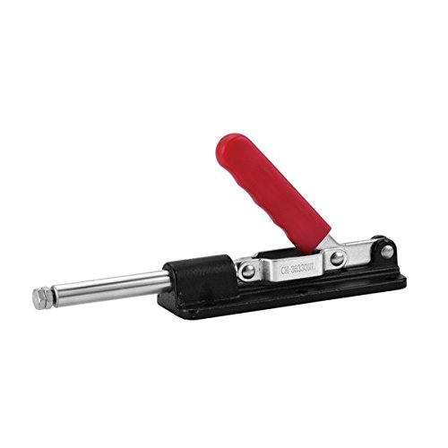
Calculate Minimum Clamping Force for Your Part and Machine
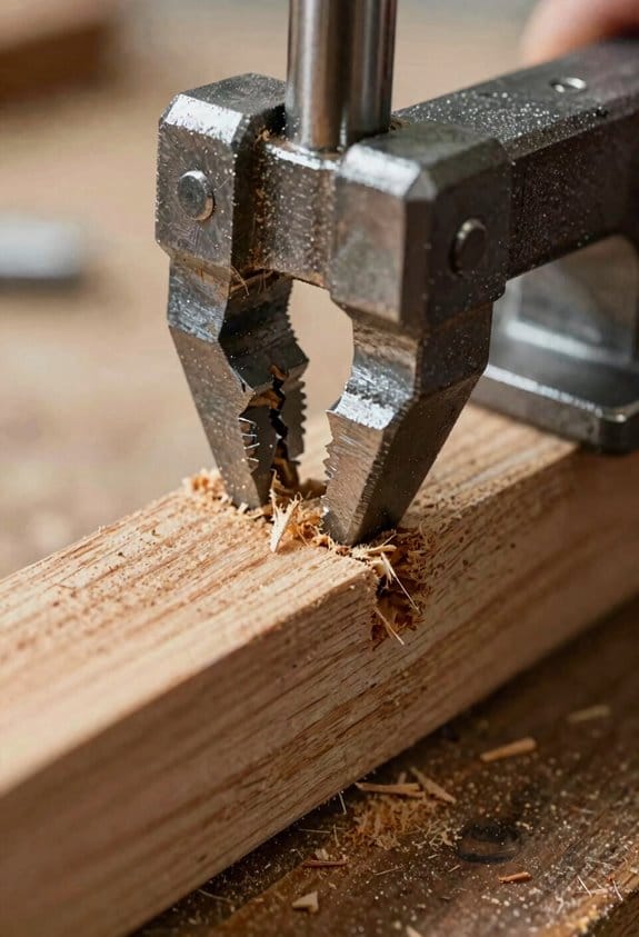
Before you calculate minimum clamping force, know why it matters: if the clamp is too weak the mold opens during pack and you get flash or ruined parts.
Here’s what actually happens when you misjudge projected area and cavity pressure: the machine nameplate can claim 500 tons but the real load during pack can spike higher, and that spike is what breaks parts or mold components. Example: a 12″ x 18″ panel (216 in² projected area) with 1,000 psi cavity pressure produces 216,000 lb of force — that’s 108 tons pushing the platen apart.
Why you should factor shrinkage before you estimate pressure: different resins relax and pack differently as they cool, so expected cavity pressure can be 10–30% lower for semi-crystalline materials than amorphous polymers. Example: nylon often packs longer and can keep pressure higher late in cycle, so expect the higher end of that range.
How to calculate minimum clamping force, step-by-step:
- Measure projected area (A) in square inches. Example: a rectangular part 12″ × 18″ → A = 216 in².
- Estimate peak cavity pressure (P) in psi during pack. Use machine logs or mold tests; if unknown, start with 800–1,200 psi for moderate parts.
- Compute raw force: Force (lb) = A × P. Example: 216 in² × 1,000 psi = 216,000 lb.
- Convert to tons: Tons = Force (lb) ÷ 2,000. Example: 216,000 ÷ 2,000 = 108 tons.
- Apply safety factor (SF). Use 1.3 as a baseline: Required tons = Tons × SF. Example: 108 × 1.3 = 140.4 tons.
- Check machine actual clamp capacity against calibration data and reduce or increase allowance accordingly.
Why verify against machine calibration: nameplate numbers can be optimistic and platen wear or hydraulic losses reduce real clamp. Example: a machine labeled 200 tons might read 180 tons on a calibrated load cell, so you’ll need to plan for the lower figure.
Practical adjustments and checks you should do:
- If the part uses a high-shrink engineering plastic, decrease estimated cavity pressure by 10–20%.
- If you have in-mold sensors or Moldwizard data, use them to replace your estimate with measured peak psi.
- If your calculated required tons is within 10% of machine capacity, plan trial runs and watch for flash, then increase tonnage or reduce cavity pressure.
One final tip: balance calculated force with production realities — try a mold trial at 90% of the calculated force first to confirm no flash, then increase to the target if needed.
Recommended Products


Linear, area and volume solutions: convert dimensions, including metric

RAPID TWO-COLOR PRINTING functionality allows users to generate clear physical records at a high speed of 4.4 lines per second; this professional desktop unit utilizes a 2-color ribbon system to highlight positive and negative figures clearly.
Where to Place Clamps and the Sequence That Minimizes Variation
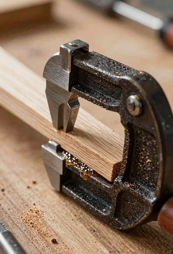
If you’ve ever tried to hold a thin aluminum plate flat while you measure it, this is why clamp placement matters. You want consistent contact so your measurements don’t wander by tenths of a millimeter.
Why it matters: uneven clamping bends parts and shifts datum points, so your sensor readings change between setups.
1) Where to place clamps
- Step 1: Identify three stable datum points near the part’s supports; pick locations over solid material, not over thin ribs. Example: on a 300 mm × 200 mm plate, choose points 25 mm in from each corner on the long edges.
- Step 2: Place clamps within 10–30 mm of those datum supports and at least 50 mm away from any section less than 3 mm thick. For the 300×200 plate with 2 mm thin tabs, move clamps to the center of the thicker zones.
- Step 3: Balance clamps symmetrically across the part so forces cancel. If you use four clamps, mirror them across both axes.
Real-world example: a technician clamping a 300×200 mm aluminum plate avoided warping by moving clamps 20 mm in from corners and away from 2 mm ribs; variance dropped from 0.15 mm to 0.04 mm.
Why it matters: the order you tighten changes how the part deforms under load.
2) Sequence and torque to minimize variation
- Step 1: Start at the most constrained datum (the reference point you won’t move) and work toward the least constrained. Example: tighten Datum A, then B, then C.
- Step 2: Use incremental torque: apply 30% of final torque first, then 60%, then 100%. If final torque is 5 N·m, tighten in passes at 1.5 N·m, 3.0 N·m, and 5.0 N·m.
- Step 3: Tighten symmetrically in each pass: for four clamps, tighten in an X pattern (top-left, bottom-right, top-right, bottom-left) during each torque increment.
Real-world example: on a fixture with four clamps and 5 N·m final torque, an inspector used 1.5/3.0/5.0 N·m passes in the X order and reduced run-to-run centroid shift from 0.12 mm to 0.03 mm.
Why it matters: documenting the process keeps operators consistent.
3) How to document and repeat it
- Step 1: Draw the fixture with clamp positions marked and label each clamp (A, B, C, D). Put distances from edges (for example: A = 25 mm from left, 20 mm from top).
- Step 2: Record the tightening sequence and torque passes (for example: A → B → C → D at 1.5/3.0/5.0 N·m).
- Step 3: Add a photo of the part in the fixture with clamps engaged and the gauge reading at setup.
Real-world example: a shop pinned a diagram and photo to the fixture; new operators reproduced the setup within 0.02 mm of the original.
Quick tips
- Use soft jaws or pads when clamping thin sections; they spread force and reduce local bending.
- If one clamp causes local flex, move it 10–30 mm away or add a support under that area.
- Check a known reference gauge after setup; if it reads outside tolerance, unbolt and repeat the torque sequence.
If you follow these concrete steps — specific clamp locations, the center-out incremental torque sequence, and a labeled diagram with a photo — your measurement variation will drop and operators will get repeatable results.
Recommended Products

Economical Steel-Welded Construction: Cost-effective steel-fabricated body (vs cast iron) significantly reduces weight while maintaining 16-gauge mild steel cutting capacity—ideal for budget-conscious workshops requiring reliable performance

RitFit Home Gym Package gets you everything you need in just one click. It helps you to customize a fully-functioning fitness space at home.

Metal Cutting Band Saw - BS-712R cuts round stock up to 7 in and rectangular stock up to 7 x 8.25 in at 90 degrees, making it suitable for metal fabrication, repair, maintenance, and shop cutting work.
When to Use Power Clamping vs Manual for Consistent Clamping Force
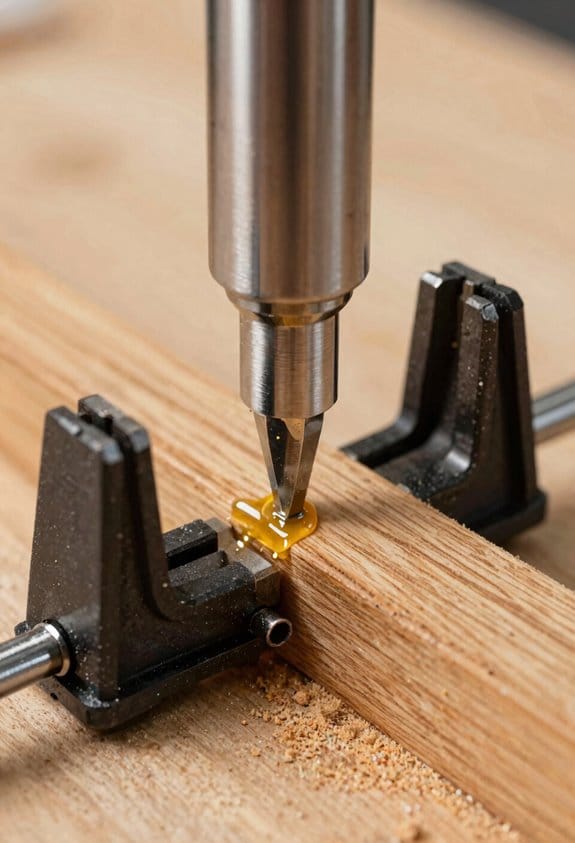
If you’ve ever wondered which clamp to pick for repeatable work, this tells you what matters: consistent clamp force cuts part variation and speeds production.
I recommend power clamping when you need repeatability and speed because it gives adjustable, repeatable force across many parts. For example, in a batch of 200 machined brackets you can set a power clamp to 500 N and activate four clamps at once, so every bracket sees the same hold-down force and cycle time drops by about 30%. Manual clamping works when you only have a few parts or weird shapes that don’t fit a powered fixture. Picture a one-off prototype with odd fixturing where you need to eyeball orientation; a hand clamp gets you there fast.
Why this matters: power clamps reduce operator fatigue and human error, which lowers scrap and rework. On a production line that runs two 8-hour shifts, switching from manual to power clamping often cuts clamp-related defects by half and reduces operator strain complaints. Use manual only when flexibility trumps consistency—like odd geometries or remote spots you can’t route pneumatics to.
How to choose between them — quick steps:
- Measure your run size and tolerance: if you run more than 50 identical parts and need +/-0.1 mm or better, go power.
- Check fixture access: if you can mount clamps and route air or power without blocking tooling, power is viable.
- Decide force and repeatability: specify target clamp force (for example, 300–800 N for light fixtures, 1–5 kN for heavy parts) and require repeatability within ±5–10%.
- Estimate ROI: compare cost of a powered clamp + valves and piping versus time saved per part; if cycle time improves by 20% or defect rate drops 10–20%, you’ll usually pay back within months.
- Use manual clamps when you need quick changes, odd geometries, or you have fewer than ~50 parts per run.
A real example: a small shop producing 500 stamped plates per week switched to pneumatic toggle clamps set to 600 N. They reduced cycle time by 25% and scrap from misclamping by 60%, paying for the clamps in under four months.
Ergonomics and layout tips:
- If operators must apply more than 50 N repeatedly, go powered to avoid fatigue.
- Mount power clamps so they don’t interfere with tooling paths; leave 10–20 mm clearance from cutting edges.
- If you need simultaneous action, use a single-valve manifold or an electrical sequencing block to trigger 4–8 clamps together.
When to stick with manual:
- Runs under ~50 pieces.
- Prototypes or one-offs with changing fixturing.
- Areas you can’t easily plumb or wire.
One more concrete note: when you specify powered clamps, list the clamp force, stroke, mounting footprint, and actuation method (pneumatic, hydraulic, or electric). That makes procurement and installation straightforward and helps the vendor match components.
Bottom line: use power clamping when your layout supports it and your process needs consistent force; use manual only when flexibility or access issues make powered systems impractical.
Recommended Products
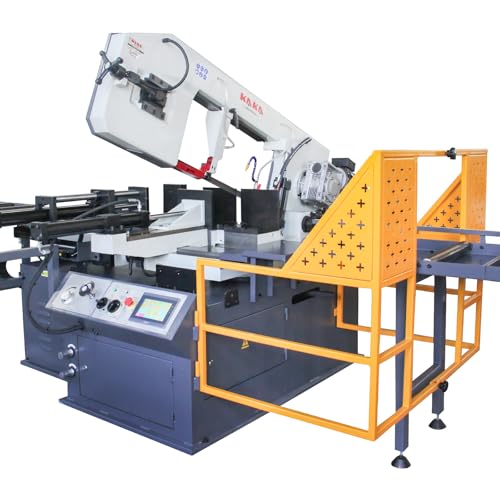
Powerful 2.2kW Motor & 4-Speed Control -Equipped with a 2.2kW (3HP), 220V single-phase motor, delivering consistent power for cutting solid steel, aluminum, and alloys. Four blade speeds (48/96 MPM) allow precise adaptation to material type and thickness, ensuring clean cuts with minimal burr

Industrial Box and Pan Brake - W-10012A is a 100 in floor model sheet metal brake designed for forming large boxes, pans, brackets, gussets, fixtures, covers, trays, and custom fabricated sheet metal parts.

ISO HYDRAULIC CONTROL & KUBOTA—POWER – Features a professional hydraulic pilot joystick system for smooth, micro-responsive operation, reducing operator fatigue during long shifts. Powered by a genuine Kubota-Diesel Engine, this compact excavator delivers consistent torque and meets strict EPA emission standards for residential and commercial projects.
Common Clamping Mistakes, Quick Checks, and Troubleshooting
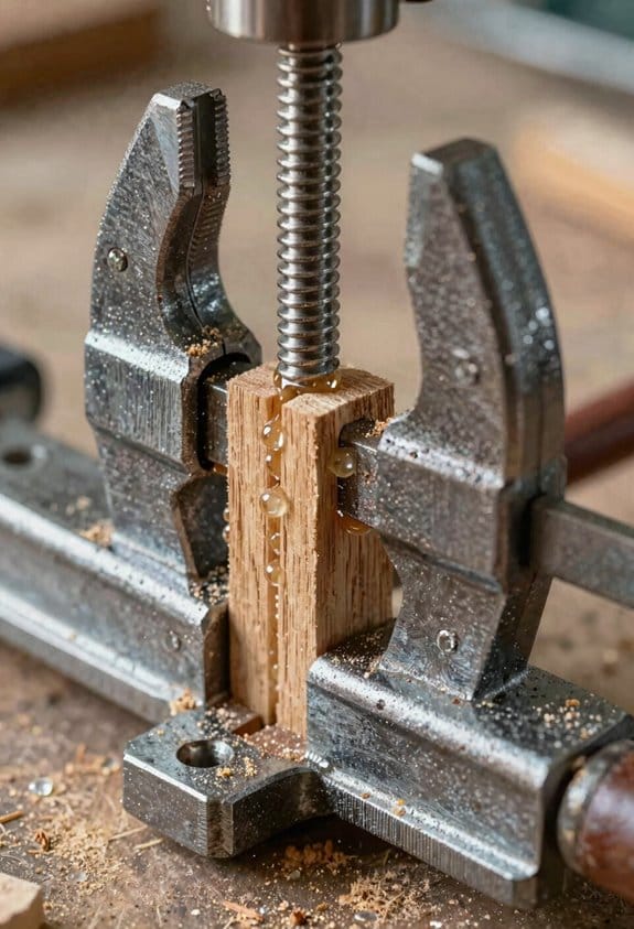
If you’ve ever had parts walk or shift during machining, this is why. You lose tolerances when clamps don’t apply consistent force or when their sequence lets the part rotate under cut. A gearbox housing I checked once had a 0.5 mm runout caused by a missed clamp—visible when I ran a feeler gauge between housing and fixture.
Why consistent clamp sequencing matters: it prevents your part from pivoting and keeps datums stable. How to check it:
- Mark clamp order with numbers on tape so you can follow the same sequence every cycle.
- Run three trial parts and measure a critical dimension each time; record the values.
- If variation exceeds your tolerance (for example, >0.05 mm), change the sequence and repeat.
Example: on a bracket with two swing clamps and one toggle, I found sequence 2-1-3 cut variation from 0.12 mm to 0.03 mm.
Loose fixtures and mismatched clamps shift dimensions. Fix these by tightening mounting bolts to a set torque and matching clamp types to the load path. Steps:
- Torque fixture base bolts to the spec—use 25 N·m for M8 steel bolts as a common starting point unless your fixture manual says otherwise.
- Replace a low-profile clamp with a higher-force clamp when the cut depth is over 3 mm and vibration appears.
- Re-inspect after 5 parts.
Example: swapping a 200 N toggle clamp for a 600 N strap clamp stopped a thin plate from bending during facing.
Ergonomics affects repeatability because manual torque varies with posture and fatigue. Why this matters: inconsistent operator force changes clamp preload and part position. How to fix it:
- Train operators on stance: feet shoulder-width, one hand on tool, one bracing fixture.
- Use torque-limiting screwdrivers or preset wrenches—set them to 10–15% above the clamping spec so you don’t under-tighten.
- Audit operators weekly by having them clamp a test piece; measure variance.
Example: after a 30-minute training, a team reduced clamp torque spread from ±20% to ±5%.
Material compatibility matters because soft or coated parts deform under hard contact, which ruins dimension. How to address this:
- Identify the part surface: soft alloy, painted, or plated.
- Use soft contact pads—rubber or PTFE pads of 2–3 mm thickness—for parts with coatings.
- For thin-walled parts, distribute force with a wider clamp foot or a supporting sacrificial plate.
Example: using 3 mm PTFE pads on anodized aluminum stopped edge marring and held dimensions within 0.02 mm.
Quick troubleshooting: isolate one variable at a time so you can find the actual cause. Steps:
- Swap only one element—change a clamp or the sequence, not both.
- Run one test part and measure the critical feature.
- If the issue persists, revert the change and try a different single variable.
Use a go/no-go gauge to confirm a fix before full production: pass/fail check takes under a minute per part.
Example: swapping clamp location (not type) on a flange cut run eliminated a 0.1 mm offset on the first trial and passed the go/no-go immediately.
Keep a one-page checklist at the station. Include clamp sequence, bolt torques, pad type, and the go/no-go dimension. Put the checklist inside the fixture drawer so you’ll see it every shift.
Recommended Products

Tilt deck kits make loading and unloading of your trucks, tractors, and equipment of any type much easier. No heavy ramps to raise or lower. Drive on and you are ready to drive away.

Aputure 300d Mark II is 20% brighter, more durable, more portable, and more intelligent than the original 300d. Change the way you light.
Aputure 300d Mark II is 20% brighter, more durable, more portable, and more intelligent than the original 300d. Change the way you light.
Frequently Asked Questions
How Does Ambient Temperature Affect Clamping Force and Dimensional Stability?
Ambient temperature shifts alter clamping force via thermal expansion, so I monitor thermal cycling closely; I’ll adjust clamps to maintain dimensional stability, since temperature-driven expansion/contraction directly changes preload and can warp measurements.
Can Clamp-Induced Stress Cause Long-Term Part Warpage After Ejection?
Yes, I believe clamp-induced residual stress can cause long-term ejection distortion; I’ve seen clamps create internal stresses that relax post-ejection, warping parts over time and shifting dimensions beyond initial inspection tolerances.
Are There Sensor-Friendly Clamp Materials to Reduce Measurement Interference?
Yes — I recommend conductive coatings on nonmagnetic alloys to reduce sensor interference; I’ll choose soft conductive plating or copper-nickel nonmagnetic alloys, ensuring consistent contact and minimal magnetic or electrical disturbance for accurate measurements.
How Do Multi-Cavity Molds Change Optimal Clamping Strategies?
Like tuning an orchestra, I adjust clamps for multi-cavity molds to make certain balanced fill and staggered gates work harmoniously; I stagger clamp sequence, equalize force across cavities, and prioritize sequence to minimize distortion and dimensional drift.
Can Clamping Strategy Impact Downstream Assembly Fit and Function?
Yes — I’ve seen clamping strategy alter assembly alignment and breach functional tolerance, so I adjust clamp sequence and force to stabilize dimensions, ensuring parts consistently meet alignment requirements and preserve downstream fit and function.