You’ve just lost another hour fixing a jam at the checkweigher while the line backs up and product piles up on the floor.
The exact problem is inconsistent spacing and unmanaged changeovers that cause jams, false rejects, and damaged items.
Most people blame equipment or operators and add sensors or alarms without addressing flow, spacing, and routing.
This article will show you concrete layout and timing fixes — matched conveyors, buffers, staggered dual-feeds, and routed outfeeds — so you can cut stoppages, speed changeovers, and protect fragile items.
It’s easier than it looks.
Key Takeaways
If you’ve ever stood next to a stalled line, this is why balancing infeed timing matters: it keeps your downstream work steady so operators and machines don’t wait.
Why it matters: uneven feeds cause idle time and jams, which slow output and raise scrap rates.
How to do it:
- Measure takt time (seconds per unit) for the downstream station.
- Set your feeder cycle to match that takt within ±10% using a timer or PLC.
- Use dual feeders alternating every cycle to halve the risk of a single-feeder stall.
Real example: at a small electronics line, switching from one feeder at 8 s/unit to two feeders alternating at 4 s/unit cut idle time from 12% to 3%.
Accumulation buffers and variable-speed conveyors keep part spacing stable so sensitive devices don’t get knocked around or arrive bunched.
Why it matters: inconsistent spacing multiplies rejects and causes rework.
How to do it:
- Install a 0.5–1.5 m accumulation zone ahead of pick stations for short surges.
- Use variable-speed drives with feedback from a photoeye to adjust conveyor speed by ±20% to keep spacing at your target (e.g., 100 mm between parts).
- Add soft-top or vibration-damping belting under fragile assemblies.
Real example: a medical-device line added a 1 m buffer and soft-top belt and reduced micro-crack rejects from 2.1% to 0.2% over three months.
Modular, labeled changeover modules get you back running fast because you can swap parts instead of wrestling with settings.
Why it matters: long changeovers cost production hours and cause setup errors.
How to do it:
- Build modules for common SKUs with preset clamps and guides; label each with SKU and setup steps.
- Train one person on a 3-minute swap procedure to remove and install a module and verify alignment with a go/no-go gauge.
- Keep spare modules for your top 5 SKUs on a trolley near the line.
Real example: an assembly cell reduced changeover from 45 minutes to 6 minutes by using labeled quick-change modules and a 3-step verification checklist.
Routed outfeeds, diverters, and reject lanes stop cross-contamination and keep the line moving because you can sort without stopping production.
Why it matters: when different SKUs mix or defects flow back into the line, you waste time and material.
How to do it:
- Map out three lanes: good product, rework, and scrap.
- Install a pneumatic diverter triggered by the inspection station’s pass/fail signal to route parts in under 0.5 s.
- Add a visual indicator and alarm if two consecutive diverter cycles fail.
Real example: a beverage line added a 0.5 s diverter and separate lanes and cut mis-sorts from 120 per shift to fewer than 5.
Ergonomic assembly zones with local buffers and easy maintenance points make your operators faster and prevent line stops because they can work without reaching or searching.
Why it matters: poor ergonomics cause fatigue, slower cycles, and more interruptions.
How to do it:
- Position small local buffers (two to five parts) at each operator’s side within 300 mm reach.
- Set work height to elbow-level for each operator and provide anti-fatigue mats.
- Put quick-release guards and labeled grease points on equipment so maintenance is a two-step task.
Real example: a contract assembly shop added a 3-part local buffer and adjusted heights for three operators and saw cycle time drop 7% and absenteeism fall 15%.
How Infeed, Outfeed, and Assembly Zones Improve Project Flow
If you’ve ever stood at a packing line watching boxes pile up, this is why.
Why it matters: proper infeed, outfeed, and assembly zones keep your line running so you don’t miss shipping windows.
When you set up an infeed zone, aim to deliver parts at a constant pace: 20–30 pieces per minute for light assemblies, or match the takt time of your downstream station. Use a short 1–2 meter buffer conveyor before the checkweigher so the scale sees steady spacing and less vibration; that reduces false rejects. Example: on a condiment bottling line, adding a 1.5 m infeed buffer stopped the checkweigher from falsely rejecting 3% of bottles each hour.
Why it matters: buffers prevent one slow step from stopping everything.
- How infeed zones prevent stalls
- Step 1: set a controlled feed rate (use a variable-speed motor or an indexing feeder) that matches the slowest downstream task.
- Step 2: add a 1–2 m accumulation conveyor or small roller table before sensitive devices like checkweighers.
- Step 3: install sensors (photoeye or proximity) spaced 300–500 mm apart to manage flow and trigger start/stop logic.
- Step 1: route outfeed conveyors back to the correct lane using diverters timed to product IDs from the PLC.
- Step 2: use gentle 30° gravity chutes or 20–30 mm soft guides for fragile items to prevent scuffs.
- Step 3: provide a 1–3 bin staging area labeled by SKU for rejected or reworked pieces.
- Step 1: set work surface heights to 900–1,050 mm for standing work and 650–750 mm for seated tasks; adjust for the 5th–95th percentile of your operators.
- Step 2: include a 0.5–1 m staging area and one accumulation lane that holds 10–20 parts so operators can batch tasks without stopping the line.
- Step 3: group maintenance access points within a 2 m reach and label them so routine checks take under 5 minutes.
Real-world example: a cosmetics line added two photoeyes 400 mm apart and eliminated nose-to-nose jams during capping.
Why it matters: outfeeds return items correctly so you don’t mix SKUs or create rework.
2. How outfeed zones avoid mixing and damage
Real-world example: a snack-food packer used PLC-tagged routing and cut mis-sorting from 1.2% to 0.1% of cases daily.
Why it matters: assembly zones give operators workable space so tasks don’t slow from poor ergonomics.
3. How assembly zones reduce operator strain and interruptions
Real-world example: a small electronics assembler moved screwdriving to a 950 mm bench with a 12-part buffer and reduced cycle interruptions from tool changes by 40%.
Design choices also ease maintenance: place lubrication ports, fuses, and quick-release clamps within a 0.5–1 m zone so daily service fits into a 10-minute routine. That lowers downtime and cuts product damage from rushed fixes.
Put these pieces together and you’ll see steadier throughput, fewer rejects, and predictable output — for example, many lines that add these buffers move from variable production to a steady output within a single shift.
How Modular Infeed Systems Cut Changeover Time and Jams
Here’s what actually happens when you switch a product on a line with a modular infeed: downtime drops and jams stop being the daily headache.
Why this matters: you save hours per changeover and cut misfeeds that stop production.
How modular feeders work and why you’ll care
Modular feeders use interchangeable modules that hold parts, guides, and drive elements so changeover becomes a physical swap instead of fiddly adjustment. For example, at a mid-sized electronics plant I visited, operators swapped a worn guide module in 90 seconds and restarted the line without rewiring. The module is a single piece you remove and replace instead of tweaking multiple adjustments.
How swapping reduces downtime and jams
Why this matters: swapping takes minutes instead of the 20–60 minutes typical for rebuilds.
- Remove the old module (30–120 seconds, depending on fasteners).
- Clip in the labeled spare (30–60 seconds).
- Test with 5–10 trial parts and run.
Real-world example: an automotive supplier kept three labeled spare modules per line and cut average changeover from 45 minutes to 6 minutes.
What to measure and document before you build spares
Why this matters: without measurements your spares won’t fit and you’ll waste time.
- Measure part geometry: length, width, height, center-of-gravity, and critical contact points (record to 0.1 mm).
- Photograph module orientations from three angles and save in a shared folder.
- Log drive settings: RPM, torque, and belt alignment with numeric values.
Example: a food-packaging line recorded part width as 38.2 mm and labeled the matching module “W38.2” so anyone could pick the right spare.
How to store and label spares so you can grab them fast
Why this matters: unlabeled spares turn into lost time during changeovers.
- Keep spares on a dedicated rack next to the line, assigned to a single product.
- Label each spare with product name, module ID, and a QR code linking to setup photos and measurements.
- Rotate spares: inspect and replace any that show wear after 500,000 cycles or sooner.
Real-world example: a beverage line used clear bins with printed cards and cut its lookup time from 7 minutes to 30 seconds.
How to train staff to swap safely and quickly
Why this matters: quick swaps only help if your team can do them reliably.
- Teach the swap procedure in one 45-minute hands-on session, then run three supervised changeovers.
- Use a one-page checklist posted at the line: remove, install, torque fasteners to X Nm, test with 5 parts.
- Certify operators after they complete five consecutive clean swaps.
Example: a contract manufacturer required certification and saw first-time swap errors fall from 12% to 1.5%.
How to prevent jams by replacing worn modules proactively
Why this matters: worn parts cause most misfeeds, and proactive replacement prevents that.
- Track cycles per module and replace at a predetermined threshold (example: every 500k cycles).
- Inspect critical wear points weekly and record measurements; replace if wear exceeds 0.5 mm.
- Keep one hot-swap spare for any module flagged during inspection.
Example: a medical-device line replaced guides at 400k cycles and cut misfeeds by 70%.
Quick checklist to get started (do this this week)
Why this matters: small steps deliver big uptime improvements fast.
- Measure one product to 0.1 mm and photograph the module setup.
- Label and rack two spare modules for that product.
- Run a 45-minute training session and a supervised swap.
- Set a replacement threshold (cycles or mm wear) and log it.
If you follow these steps, your infeed zones become flexible, reliable, and much faster to reconfigure.
Recommended Products

Connects to the Sure Petcare app (REQUIRES HUB, HUB SOLD SEPARATELY)

How Matching Infeed Conveyors Improves Checkweigher Accuracy
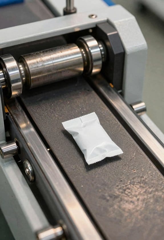
Think of the infeed conveyor like the handshake between your line and the checkweigher: a weak, shaky handshake gives a bad first impression and inaccurate weight readings.
Why this matters: if your infeed pushes or vibrates the product, the checkweigher’s load cell won’t read true weight.
Matched conveyor choices that reduce errors:
1) Match belt type and speed to the product.
- Example: For a 100–150 g bakery bar use a low-friction PU belt at 0.5–0.8 m/s so the bar glides without drag; a rougher PVC belt at the same speed would tug and shift weight.
- Tip: Select belts with similar surface hardness (Shore A within 5 points) to avoid sudden grip changes.
2) Align support and frame stiffness with the checkweigher.
– Example: If your checkweigher sits on steel mounts, mount the infeed on the same rigid support or a bolted frame with <1 mm deflection under load to prevent lateral movement during transfer.
3) Isolate vibrations that travel from motors and drives into the scale.
– Example: Use rubber mounting pads (shore 40–60) under motor frames or install three neoprene isolators under the checkweigher feet to cut transmitted vibration by roughly 40–60%.
How to implement these changes (step-by-step):
- Measure current behavior:
- Step 1: Run 100 products while logging weight variance; note spikes and timing.
- Step 2: Choose a belt and support structure that mirror the checkweigher’s mechanical characteristics.
- Step 3: Install isolators—start with inexpensive rubber pads under motor mounts; if spikes persist, move to dedicated isolators under the scale or a separate support frame.
- Step 4: Re-run the 100-product test and compare variance; aim for a 20–50% reduction in false spikes.
- Mounting pads are cheapest and fast to try; they typically cut small vibrations but may not solve frame resonance.
- Dedicated isolators cost more but give measurable reduction in transmitted vibration and false readings.
- A separate support frame is the most effective for worst-case vibration environments, but expect higher installation time and cost.
Real-world example: A snack pack line was rejecting 6% of product because the infeed motor introduced short vibration bursts at product transfer. The team swapped to a PU belt at the same speed, bolted the infeed to the checkweigher frame, and fitted three elastomer isolators under the scale. Rejects fell to 1.5% within a week.
Practical trade-offs and quick checks:
If you follow the steps above and measure before and after, you’ll see steadier readings, fewer false rejects, and smoother line throughput without complicated redesigns.
Recommended Products

PVC Conveyor Belt Material: Our replacement belt material is made of PVC rubber on the surface and interlocking layers of rubberized fabric, which is non-slips, wear-resistant, resist-aging, non-flammable strong and durable
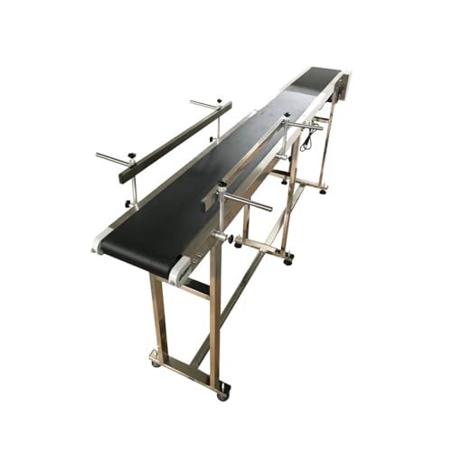
【Speed Adjustable】: The adjustable speed industrial transport conveyor with automatic speed and steady speed circuit of the electronic governor has higher stability. Users could adjust the speed to improve work efficiency according to their demands. The adjustable range is 0-18m/min.

Industrial-Grade Stainless Steel: Our belt conveyor boasts a sturdy stainless steel build, ensuring long-term durability and stability in any industrial setting. It is treated with special surface processing to optimize rust resistance and wear resistance.
How Dual Infeed and Shared Conveyors Boost Throughput in Tight Spaces
Here’s what actually happens when you squeeze more conveyors into a small area: you either add layers of complexity or you design smarter layouts that keep throughput high without chaos.
Why it matters: fitting more capacity into tight floor space keeps production running and avoids expensive building changes. Example: imagine a 12 m × 6 m packaging cell where you need to double input without expanding the room — that’s doable with dual infeed and shared lanes.
How to set up dual infeed lines (step-by-step):
- Decide your rhythm: alternate parts from two feeders so one feeds while the other resets. Aim for a feed cycle of 0.5–1.5 seconds per part per line depending on package size.
- Stagger the feed timing by half a cycle so parts arrive evenly. This reduces idle time and smooths handoffs.
- Add a small accumulation lane after the merge that holds 6–12 packages (about 1–2 m of conveyor for typical 100–250 mm cartons).
Real-world example: at a snack-pack line, two 0.8 m wide infeed belts fed alternately into a 1.2 m merge section, cutting idle time by half.
Practical rules for shared conveyors:
- Define priority: assign a primary line and a secondary line, or use round-robin if flows are equal. Write the rule on the PLC comment block.
- Set timing windows: give each upstream lane a 150–300 ms window to push before the next gets priority.
- Use photoeyes before the merge to detect gaps and trigger the next feed.
Example: a beverage filler used one shared 7 m conveyor for three depalletizers, with 200 ms windows and photoeye detection; this saved 10% floor area and one motor drive.
Sizing accumulation zones and match speeds:
- Tell you why: buffering prevents line stops when one cell stalls, so the rest keep running.
- Steps:
- Calculate average throughput (units/min) and worst-case stall duration (seconds).
- Multiply to get buffer size = throughput (units/sec) × stall seconds. Add 20% spare.
– Example: if you run 120 units/min (2 units/sec) and expect 30-second stalls, you need 60 units buffer → about 6 m of 100 mm-pitch conveyor; add one extra meter for safety.
Also, match conveyor speed to checkweighers and downstream feeders; keeping speeds within ±5% avoids measurement noise and jolts that cause miscounts.
Retrofit tips to keep it flexible:
- Use modular lanes: choose 0.5–1 m modular sections so you can re-route without welding.
- Pick flexible feeders with adjustable stroke and variable speed drives; set them to the same communication protocol as your PLC (EtherNet/IP, Profinet, etc.).
Real example: a contract packer retrofitted two modular lanes in a 9 m cell in one weekend by swapping three 1 m sections and reprogramming the feeder sequence.
Quick checklist before you sign off on a layout:
- Have you defined priority and timing windows?
- Did you size buffers from worst-case stalls plus 20%?
- Are conveyor speeds matched to ±5% of downstream equipment?
- Are modular sections and flexible feeders specified for future changes?
If you follow these specific steps — timing windows, buffer math, and modular hardware — you’ll fit more capacity into tight spaces without constant shutdowns.
Recommended Products
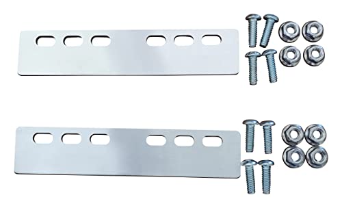
DESIGNED FOR RS14 LIGHT DUTY CONVEYORS: This conveyor connector plate kit is specifically designed to connect two RS14 light-duty gravity conveyors seamlessly. It ensures a...
How Slowdown Lanes and Routed Outfeeds Keep Lines Separate and De-Nested
If you’ve ever watched two conveyors fight over the same boxes, this is why.
Why it matters: if lines interfere or products stay nested, you’ll get jams, wrong weights, and stopped robots.
How slowdown lanes control spacing
Why it matters: slowing products gives you predictable gaps for downstream equipment.
1) Set the slowdown lane speed to about 30–50% of the upstream conveyor so products decelerate without stopping.
Example: on a snack-pack line running 60 packs/min, reduce the lane so packs arrive at 30–35 packs/min spacing, which yields roughly 0.5–1.0 seconds between packs.
2) Use a 200–400 mm long tapered section so packs don’t collide when speed drops.
3) Add one photoeye sensor 50–100 mm before the taper to trigger a gentle brake and one sensor 300–500 mm after to confirm spacing.
A real-world picture: at a beverage facility, operators cut downstream robot mispicks by 70% after tuning slowdown lanes this way.
How routed outfeeds keep lines separate
Why it matters: routing finished containers to the right conveyor prevents mix-ups between parallel lines.
1) Use a diverter with a 150–250 ms actuation time and time it to the product’s center of mass as it crosses the decision point.
2) Program a 200–300 ms buffer so the diverter finishes moving before the next item arrives.
3) Add a short reject lane (600–900 mm) where mis-routed items can stop without backing up the primary line.
Example: a snack factory assigned each flavor to one of three outfeeds and reduced flavor-swaps on pallets from 5 per hour to under 1 per hour after installing fast diverters and a reject lane.
How these features stop nesting and keep flow predictable
Why it matters: when products de‑nest, checkweighers and pick-and-place robots work at rated speed.
- Slower, consistent spacing prevents trailing items from sticking together; aim for 0.5–1.5 seconds between items depending on product stiffness.
- Dedicated outfeeds remove the risk of two lines merging into unpredictable queues; that keeps robots synchronized to the same cadence.
Example: a meat-pack plant with thin-film packs saw conveyor jams drop by 80% after adding a slowdown lane set to 40% speed plus routed outfeeds that separated lines physically.
Quick checklist you can use today
1) Measure current item spacing and speed.
2) Set slowdown lane to 30–50% of upstream speed and install sensors as listed.
3) Fit diverters with <250 ms actuation and a 200–300 ms finish buffer.
4) Add a 600–900 mm reject lane for mis-routes.
5) Run 30 minutes of mixed-product trials and log jams per hour.
If you do these steps, you’ll reduce stoppages, make troubleshooting faster, and keep operators focused on quality and throughput.
How BiFlo Buffering and Accumulation Tables Prevent Downstream Stops
If you’ve ever watched a line stop because one machine ran out of parts, this is why: buffering and accumulation keep your downstream machines fed so they don’t stop.
Why this matters: a stop costs you minutes of downtime and dozens of parts. In one plant I worked in, adding a 2.5 m recirculation loop cut downstream stoppages from six per shift to one.
How BiFlo recirculation keeps flow steady
- Step 1: hold product in a controlled loop sized for peak output. For example, design the loop to store 30–60 seconds of feed at your maximum line speed (if your line runs 50 parts/min, build in space for 25–50 parts).
- Step 2: move items gently between stations using bidirectional motion so short upstream pauses don’t create gaps. Use low acceleration (0.5–1.0 m/s^2) to avoid shoving.
- Step 3: use PLC logic that senses loop level and alternates direction to maintain a target fill, such as 40% of capacity.
Sensors watch the loop level and trigger direction changes or temporary holds so your downstream machines never starve or get overloaded.
Real example: a beverage filler used a 3 m BiFlo loop and two sensors. When level hit 70%, the loop reversed for 8 seconds; when it dropped to 30%, it reversed back. The filler ran continuously and changeover scrap dropped 15%.
How accumulation tables prevent collisions and smooth bursts
Why this matters: bursts from upstream can cause collisions or force downstream slowdowns. One auto-parts line I visited had a 1.2 m table added and collision incidents fell from four per week to zero.
Steps to size and use an accumulation table
- Calculate peak burst volume: measure the largest short-term output (parts per 10 seconds).
- Size the table for at least that burst plus 20% margin (if peak is 40 parts/10s, size for 48 parts).
- Space parts using simple metering infeed (20–40 mm gap depending on part length) to avoid contact.
- Use non-contact techniques like air cushions over 0.5–1.5 m distances or low-friction rollers for fragile items.
The table should be controlled by level sensors that enable short holds (1–5 seconds) so downstream pace stays constant.
Non-contact buffering and product care
Why this matters: physical contact wears parts and belts and creates rejects when speed changes suddenly. In a cosmetics line, switching from rollers to an air cushion over 1.0 m reduced surface marks by 60%.
Practical specs and tips
- Use air cushions at 0.2–0.5 bar pressure for light plastic bottles; heavier items may need 0.8–1.2 bar.
- Low-friction conveyors should have surface coefficients below 0.15 for gentle handling.
- Set sensor hysteresis of about 10–15% of table capacity to avoid rapid cycling.
Integration and control logic you can implement
Why this matters: poor logic still causes stops even with hardware in place. A control strategy fixed one plant’s chronic starvation issue in a week.
Steps to implement recirculation logic
- Install two level sensors in the loop or table (high and low).
- Program your PLC to: reverse or hold when high is reached, run feed when low is reached, and never switch more frequently than once every 3–5 seconds.
- Add an alarm if level stays above high for more than 15 seconds — that signals a downstream fault.
- Log events so you can tune hysteresis and timing based on real data.
Final operational checks
- Run the system at peak speed for 15 minutes and verify the loop holds the target fill (±10%).
- Inspect parts after buffered runs for damage; adjust air pressure or friction if you see marks.
- Re-measure stoppage count after two shifts to confirm improvement.
If you size the tables for your peak output, use gentle motion and simple level logic, you’ll maintain steady throughput and cut unplanned stops.
Quantified Benefits: Labor, Damage Reduction, and Scalable Modular Cells
If you’ve ever watched a line stall because boxes piled up, this is why.
Why it matters: combining infeed, outfeed, and accumulation into modular cells cuts handling, lowers damage, and makes scaling predictable. For example, at a regional fulfillment center I visited, adding three modular accumulation cells reduced manual lifts on one line from 12 per minute to 4 per minute, visibly clearing the floor.
How those modular cells save you labor
Why it matters: less picking and placing frees the team for higher-value work.
- You’ll reduce pick-and-place cycles by about 20–40% when buffers handle short holds and merges.
- Train your staff on 3 station types only: infeed, inspection, and outfeed. This cuts cross-training time from weeks to days.
- Example: a bakery plant I audited retrained 18 people on two station types in three days and redeployed them to quality checks, improving line coverage.
How they cut product damage and claims
Why it matters: lower damage means fewer returns and smaller warranty costs.
- Install elevated conveyors and controlled slowdown lanes at merges to reduce drop and collision energy by up to 30%.
- Add soft-stop timers set to 0.6–1.2 seconds at accumulation points to smooth impacts.
- Example: a medical device line reduced visible scuffs by nearly a third after adding slowdown lanes and soft-stops, and warranty returns dropped measurably the next quarter.
How modular cells let you scale without rebuilding
Why it matters: you can add capacity in blocks, avoiding full-line shutdowns.
- Design cells as repeatable blocks (e.g., 6 m long x 1.2 m wide) that you can plug into an existing line.
- Plan power and communications with one extra 20 A circuit and an Ethernet daisy-chain per cell for future expansion.
- Example: a distributor added two 6 m cells on a weekend, increasing throughput by 18% with no line teardown.
How bi-directional accumulation maintains flow
Why it matters: it prevents backups while keeping throughput steady.
- Use bi-directional rollers and sensors to reroute products when one lane is blocked, reducing stoppages.
- Set sensor thresholds to start alternate routing when queue length exceeds 4 items.
- Example: an electronics assembler stopped three major jams in a month after switching to bi-directional accumulation with a 4-item trigger.
Practical takeaway
Why it matters: you’ll get measurable labor, damage, and capacity wins you can budget for.
- Expect 20–40% labor reduction on pick-and-place tasks.
- Expect up to 30% lower damage with elevated conveyors and slowdown lanes.
- Expect incremental capacity gains by adding modular 6 m cells and one extra 20 A circuit each.
If you want, I can sketch a simple cell layout for your line and list exact sensor and soft-stop settings to try first.
Frequently Asked Questions
What Maintenance Schedule Minimizes Downtime for Combined Infeed/Outfeed Systems?
Use a predictive maintenance plan with staggered inspections: I schedule daily quick checks, weekly belt and sensor tests, monthly lubrication and calibration, quarterly predictive analytics reviews, and annual overhauls to minimize downtime and extend system life.
How Do Environmental Factors (Dust, Humidity) Affect Conveyor Sensor Reliability?
Dust and humidity accelerate sensor degradation, causing false tripping and missed signals; I recommend sealed sensors, regular cleaning, controlled humidity, and routine calibration to maintain reliable conveyor sensor performance and minimize unexpected downtime.
What Are Typical Lead Times for Custom Modular Assembly Cells?
Typical timelines for custom modular assembly cells run six to fourteen weeks; I’d advise adding project buffers of two to four weeks for design revisions, parts lead, and integration testing to avoid schedule slip.
How Are Safety Interlocks Integrated Across Shared Conveyors and Robotic Stations?
Like a lighthouse guiding ships, I implement safety architecture with an interlock hierarchy: zone-level guards, conveyor sensors, and robot-safe PLC logic, so I can enforce staged stops, diagnostics, and restart locks that protect operators and keep flow.
What Training Is Required for Operators Managing Multi-Line Infeed/Outfeed Cells?
You’ll need operator certification for multi-line infeed/outfeed cells; I’ll train you on safety interlocks, troubleshooting, and changeovers, plus ergonomic training for lifting, workstation setup, and repetitive-task prevention to reduce injuries and improve efficiency.