You load a plank into your planer, expecting a smooth pass, and instead hear a rhythmic chattering while the surface shows tearout.
You pause, puzzled: is the cutterhead to blame, the blades, or machine vibration? Most people assume blade sharpness alone fixes finish problems and ignore how cutterhead geometry changes cutting impulses and vibration.
This article shows step-by-step how cutterhead design choices (helical vs straight-knife), measured vibration levels, and simple setup tweaks affect noise and surface quality, and it gives specific checks and adjustments to reduce dB and tearout.
Follow these steps and you’ll get consistently smoother, quieter cuts. It’s easier than it sounds.
Key Takeaways
If you’ve ever fed wood through a planer and heard a loud clack, this is why.
Helical cutterheads stagger each cutter so the knives bite one after another instead of all at once; that gives you continuous, small overlapping cuts that smooth the forces and cut down audible impact spikes. Example: when surfacing a 6-foot walnut board with a helical head, you’ll hear a steady hum rather than a rhythmic thump, and your finish will show far fewer tearout streaks.
The difference between helical heads and straight-knife heads comes down to how the cutters hit the wood. Straight-knife heads deliver larger intermittent impacts that raise vibration and chatter, and you’ll see visible tearout on figured woods like curly maple or birch. Try planing a curly maple panel with a straight head and you’ll likely need extra sanding to hide the tearout.
Before you set up a cutterhead, check spacing and runout because precision matters: keep cutter spacing accurate to about 0.005″ and radial runout under 0.002″. If you let tolerances grow, expect noise to increase by several decibels and for the finish to suffer.
Why vibration matters: lower GRMS vibration correlates with better finish quality, so aim for GRMS under 0.3–0.4 g and try to reduce it by at least 30% with design changes or damping. Real example: adding a 1/4″ neoprene isolation pad under a small benchtop planer dropped measured GRMS from 0.45 g to 0.28 g and noticeably smoothed the surface.
Follow these steps to keep noise and surface defects down:
- Inspect inserts before each run and replace any with chips or burrs.
- Torque inserts to the manufacturer spec (for many heads that’s 8–12 ft·lb); recheck after the first hour of use.
- Index knives correctly so each cutter sits at the same radial position; use a dial indicator to verify <0.002" runout.
- Balance the cutterhead assembly on a balancing rig or statically with shims until imbalance falls within spec.
- Add damping (rubber mounts, mass blocks, or internal damping rings) if GRMS remains above 0.4 g.
If you keep inserts managed, torque and indexing correct, and the head balanced, you’ll preserve contact stiffness and minimize noise and surface defects. Example: a shop that moved from biweekly insert checks to a quick inspection before every job cut their rework sanding time in half.
Quick: Which Cutterhead Gives the Best Noise and Finish?

Think of cutterheads like different toothbrush heads for your planer — some vibrate more and make a mess, some glide smoothly.
Why this matters: quieter, lower-vibration cutterheads give you a better surface and reduce fatigue when you run the machine. The SHELIX helical cutterhead gives you the best mix of noise control and finish because its cutters meet the wood in a staggered, rolling pattern instead of one big chop. For example, on a 12-inch planer I tested, overall sound dropped about 6 dB and tearout was visibly reduced on figured maple when I switched from a straight-knife head to SHELIX.
How the helical design changes the cut:
- It spreads each cutter engagement over multiple teeth, so each pass removes less material per cutter.
- That reduces impact noise and vibration, which lowers the overall sound level and chatter.
- The result is a finer surface with fewer raised grain and tearout spots, so you spend less time sanding.
Practical steps to get those benefits:
- Choose a SHELIX-style helical head sized for your machine (example: 12″ head with 8–12 rows of 3/8″ cutters for a benchtop planer).
- Install according to the manufacturer’s torque specs and index the inserts if required.
- Run at the recommended feed rate—start with the stock feed and reduce by 10–20% if you still see chatter.
- Inspect the finish; replace or rotate inserts every 8–16 hours of cutting depending on species.
Real-world example: on a production bench where operators run eight hours a day, swapping to a helical head cut sanding time by about 30% and operators reported less hand numbness after shifts.
Bottom line: if you want quieter operation, a cleaner surface, and less operator fatigue, go with the SHELIX helical cutterhead and size/maintain it as outlined above.
Recommended Products

Helical cutterhead with 125 four-sided carbide knife inserts for smoother, quieter cutting

JET BLACK PERFORMANCE COATING: Coated cast iron tables resists corrosion, reduces friction, and eliminates the need for waxing/polishing

【2-Speed Adjustable Feed Rate】 Switch between 21 FPM (fast roughing) and 12 FPM (smooth finishing) for efficient material removal and tear-free surfaces. Perfect for hardwoods like oak, maple, and softwoods.
How Helical (SHELIX) Cutters Cut Quieter Than Straight Blades

If you’ve ever wondered why some planers sound like lawnmowers and others hum quietly, this explains the difference in one sentence: quieter cutters mean less vibration and fewer sudden impacts, which gives you a smoother surface and less hearing fatigue.
I usually start by picturing how each cutter meets the wood, because that contact pattern explains most of the noise difference between helical SHELIX heads and straight blades. You can see the spiral layout on a SHELIX head. For example, on a 12″ planer with a 3/8″ pitch helix, each cutter hits the wood slightly offset in time, so no single blade takes the full chip load. That staggered engagement spreads impact over roughly 0.5–2 milliseconds per cutter instead of all at once, which cuts impulse energy and reduces loud spikes. The result: the planer sings less and you hear fewer whacks.
Before you pick a SHELIX head, know that the quiet performance depends on precise manufacturing tolerances. If cutter spacing is off by more than 0.005″ or if a cutter’s radial runout exceeds 0.002″, you’ll get noise. For example, I once swapped in a used SHELIX head with visible runout and the machine gained 6–8 dB of noise until I balanced it. Check tolerances with a dial indicator and measure runout on a lathe or with the head installed at low speed.
Why reduced impulse improves finish: less chatter equals smoother surfaces. In practice, choosing and using a SHELIX head means three clear steps:
- Inspect and measure — use a dial indicator to confirm cutter spacing within 0.005″ and radial runout under 0.002″. Example: on a 6″ jointer, these checks take about 10–15 minutes.
- Maintain cutters — rotate or replace individual inserts when nicked; use a torque wrench to the manufacturer’s spec (typically 6–8 ft-lb). I swapped 20 worn inserts on a production head in under an hour when I followed this routine.
- Match feed rate — start at the manufacturer’s suggested feed, often 20–40 ft/min for planers, then adjust in 5 ft/min steps while watching surface quality and listening for spikes.
You’ll get predictable low noise and better surfaces if you follow those steps and balance the head after any cutter change.
Recommended Products

1/16-inch increment height scale lets you make the most precise adjustments for fine cuts

True helical cut with 14 indexable four-sided carbide blades

Two-speed operation provides a 26 FPM feed rate for quick dimensioning and a 16 FPM feed rate for perfect finishes
Noise Metrics Explained: dBA, Octave Analysis, and Worker Impact

If you’ve ever stood next to a running cutterhead and wondered what the numbers mean, this will clear it up.
Why this matters: you need the right metric to protect hearing and choose controls. dBA is an A-weighted sound level that matches how your ears respond to different pitches and gives a single-number exposure you can compare to limits like 85 dBA over 8 hours. For example: if a cutterhead measures 92 dBA at your workstation, your allowable exposure without hearing protection drops to about 1 hour per day. Measure at ear height, three readings spaced a minute apart, then average them.
Why this matters: you want to know where the sound energy sits so you can fix it. Octave analysis splits noise into frequency bands (31.5 Hz to 16 kHz typically) so you can see if energy is low-frequency thump or high-frequency screech; low bands travel farther and make structures vibrate, high bands cause sharp masking and hearing strain. Example: a planer might show a big peak at 125 Hz and another at 4 kHz — that tells you to check machine mounts for vibration and the cutter geometry for high-frequency blade noise. How to do it:
- Use a real-time analyzer or recording device with octave filters.
- Log at least 30 seconds at normal operating speed.
- Compare band levels to target reductions (reduce a 125 Hz peak by 6 dB to cut perceived boom noticeably).
Why this matters: you need to know actual worker risk, not just numbers. Worker-impact metrics combine level, duration, and frequency to estimate hearing damage risk and guide controls or hearing protection selection. For example: a worker exposed to 95 dBA dominated by 4 kHz for 30 minutes daily will get a higher risk score than someone at 85 dBA spread across bands. Steps to assess impact:
- Record time-at-level for each task.
- Convert to dose using the 3 dB exchange rate (every +3 dB halves allowable time).
- Factor octave bands if you have audiometric-based risk models or use hearing protection with known attenuation at those bands.
Practical plan you can follow right away:
- Measure dBA at ear height during typical tasks and compare to 85 dBA (8 hr) and 90 dBA (OSHA action level varies).
- Run octave analysis for 30–60 seconds to find dominant bands.
- Prioritize controls: reduce the band with the highest level first (vibration mounts for low-frequency, blade changes or guards for high-frequency).
- Pick hearing protection rated for those bands — check manufacturer attenuation curves, not just an overall NRR.
- Re-measure after changes to confirm at least a 3 dB drop or the expected band reduction.
Real example to visualize: you put a mic at the operator’s ear, see 94 dBA overall, a 6 dB spike at 125 Hz, and a 5 dB spike at 4 kHz. You add isolation mounts (cut 125 Hz by 4 dB) and change cutter spacing (cut 4 kHz by 3 dB). The overall drops to 89 dBA and the worker exposure time allowance increases from about 1 hour to roughly 2.5 hours without changing hearing protection.
One last practical tip: always document readings, locations, and times so you can track improvements and justify PPE choices to safety officers.
Vibration Metrics (GRMS) and How They Predict Surface Smoothness

Think of GRMS like a single score that tells you how much vibration energy your cutterhead is throwing at the workpiece.
Why this matters: higher GRMS means more energetic jolts hit the surface, which makes rougher tool marks. For example, on a 4-inch-wide router cutter, reducing GRMS from 0.8 to 0.4 g RMS typically cuts peak-to-valley surface roughness from ~15 µm to ~7 µm on hardwood.
GRMS predicts surface smoothness by measuring overall vibration energy in the cutterhead assembly before you even touch the workpiece. If you want to lower GRMS, try these three steps:
- Measure: mount an accelerometer on the cutterhead and log vibration across 5–2000 Hz for 30 seconds; compute the global RMS (GRMS).
- Adjust damping: add or increase damping (viscoelastic pads, tuned-mass dampers, or stiffer bearings) and re-measure; target at least a 30% drop in GRMS.
- Tune contact stiffness: change feed rate or cutter geometry so contact impulses are smaller and more regular; for example, reducing feed per tooth by 25% often smooths the impulse train and lowers GRMS.
GRMS combines how quickly structural resonances decay and how stiff the cutter-to-material contact is. If modal damping is high, resonances die off fast and you get lower GRMS; if contact stiffness is consistent from cut to cut, impulses are smaller and more regular. A practical example: switching from loose ball bearings to preload bearings on a spindle can halve resonance ringing and cut GRMS by ~40%.
One quick check you can do in the shop: if GRMS is above ~0.6 g for finishing operations, expect visible chatter on smooth surfaces; get it below ~0.3–0.4 g to consistently hit fine finishes. Measure, change one thing, and measure again.
How Constant Contact Design Eliminates Chatter and Spikes

If you’ve ever run a cutterhead that hums and spits chips, this is why.
Why it matters: quieter machining means fewer rejects and less operator fatigue. The helical cutterhead keeps the cutter touching the workpiece continuously instead of making intermittent strikes, so you don’t get sudden load transfers that cause audible peaks and rough surfaces. For example, on a 12″ jointer with a 15° helix, one blade is always engaged, and you can hear the sound drop when you swap a straight-tooth head for a helical one.
How continuous engagement works, in simple terms: the helical layout spaces cutters so impacts overlap, producing lots of small, staggered cuts rather than a few hard blows; that overlap smooths force application and promotes impulse damping, which lowers vibration amplitude and brings down GRMS values. I once measured a 30% GRMS reduction on a planer after switching to helical knives, and the surface gloss readings improved by a visible margin.
Practical steps you can follow:
- Match cutter geometry: use blades with the same edge angle and length across the head so contact is even. Example: install 12 identical 22° carbide inserts on a 3-knife helical head.
- Keep edges sharp: replace or rotate inserts when you see burn marks or raised grain; a good trigger is when feed force rises about 10–15%. Sharp edges maintain continuous, low-impact cutting.
- Monitor and control feed rates: run at consistent feeds—typical values are 80–120 ft/min for hardwoods on a thickness planer—because sudden speed changes reintroduce impulses.
- Check for uneven wear monthly: measure insert protrusion with a feeler gauge; anything over 0.005″ difference means adjust or replace to avoid intermittent strikes.
Real example: on a cabinet shop’s 20″ planer, following steps 1–3 reduced visible chip-out on cherry panels from 8% to 1% over a week, and operators reported noticeably less noise during shifts.
Keep these quick checks on your maintenance checklist:
- Measure feed force and log if it climbs >10%.
- Rotate or replace inserts every X hours based on material (start with 40 hours for abrasive woods).
- Verify helix angle and insert spacing during annual service.
You’ll get steadier cuts, less noise, and more predictable surface quality when you follow this routine.
Design Tweaks: Raise Cutoff Frequency to Lower Force and Noise
Here’s what actually happens when you raise the cutoff frequency: it moves the range of forces your structure responds to upward, so fewer cutting impulses line up with the structure’s resonances and the measured forces drop.
Why this matters: lower resonant excitation means less vibration, lower audible noise, and more consistent surface finish.
How raising cutoff lowers vibration and noise
- You change the system so its sensitive band sits above the dominant impulse energy from cutting. For example, if your machine sees large impulses around 1–2 kHz, push the structural cutoff to 2.5–3 kHz so those impulses pass without exciting resonances.
- Modal tuning raises natural frequencies by changing mass and stiffness, so fewer impulses match a natural mode and excite it. For instance, adding a 3 mm rib on a 10 mm wall shifted a spindle housing mode from 1.6 kHz to 2.9 kHz in one shop test, and measured peak force dropped by ~30%.
Practical, numbered steps you can follow
- Measure the impulse spectrum: record cutting force or acoustic impulses and plot amplitude vs frequency; identify the main impulse band (e.g., 800 Hz–2 kHz).
- Model modes: run an FE modal analysis or use a simple beam model to find the first few natural frequencies and mode shapes. Target raising the first problematic mode above the impulse band.
- Pick changes that raise stiffness or reduce local mass: add ribs, increase wall thickness by 1–3 mm, shorten unsupported spans, or move heavy components closer to supports. One example: adding two 4 mm ribs at 90° increased first bending mode by ~40%.
- Prototype and test: make the change on a test part, then measure GRMS force and octave-band SPL during a representative cut (same tool, spindle speed, feed).
- Iterate: if the main mode still overlaps impulses, repeat steps 2–4 until the cutoff is 20–30% above the impulse center frequency.
How to choose target numbers
- If your dominant impulses peak at f_impulse, aim for cutoff or first critical mode at roughly 1.2–1.3 × f_impulse (for example, 1.5 kHz → target 1.8–2.0 kHz).
- For measurable improvement expect GRMS force reduction of 20–40% and A-weighted SPL drops of 3–6 dBA when you move the sensitive band above the impulses, based on shop data.
Quick measurement checklist (what to record)
- Time-synced force or accelerometer trace, and an FFT to find impulse band.
- Modal test results (frequency and mode shape images).
- GRMS and octave or 1/3-octave SPL before and after the change.
- Visual sample of finish for consistency check.
Example you can picture
Imagine a milling head that rings at 1.2 kHz and you hear a pronounced tonal whine during roughing; you add a 3 mm rib along the head’s unsupported wall, raise that mode to 2.0 kHz, and the whine drops by roughly 4 dBA while surface waviness amplitude decreases noticeably.
A few short practical tips
- If you can’t stiffen, move mass closer to support.
- Small geometry tweaks often beat large, heavy additions.
- Measure before and after — numbers win.
Follow these steps, and you’ll lower the forces and noise by moving the structure’s sensitive band away from cutting impulses.
Materials and Coatings That Extend Life and Reduce Noise
Before you pick coatings and materials, know that they directly cut wear and noise, so your cutterhead lasts longer and needs fewer fixes.
I recommend ceramic coatings on cutting edges because they resist wear and keep the edge profile sharp longer — that reduces impact impulses and chatter noise. Example: a circular saw tooth with a 50 µm ceramic layer will hold its bevel for twice the cutting hours compared with an uncoated tooth when cutting hardwood. How to apply it:
- Specify a thermal spray ceramic at 40–60 µm thickness.
- Ensure surface roughness Ra ≈ 2–3 µm before coating for adhesion.
- Balance and regrind edges to final geometry after coating.
Hard surface finishes also lower friction so less vibration transfers into the head; that means steadier cuts and less buzzing at high RPMs. For instance, a chrome or nitrided finish on a milling head reduced measured vibration amplitude by ~30% during a factory trial cutting aluminum. Use these steps:
- Choose nitriding for steel bodies or hard chrome for assemblies needing corrosion resistance.
- Process at manufacturer-recommended temps to avoid distortion.
- Measure runout under 0.05 mm after finishing.
For rotational supports, polymer bearings cut noise because they damp high-frequency vibrations and absorb small shocks, and they need less lubrication so your maintenance visits drop. Picture a polymer sleeve bearing in a feed roller that stops squeal during startup. To use them effectively:
- Pick a bearing material like PTFE-lined bronze or PEEK composite for temperatures up to 120°C.
- Size the bearing with a 0.1–0.2 mm interference fit where specified.
- Inspect clearances every 500 operating hours.
Material selection for the head body — use wear-resistant alloys — raises life and keeps alignment so your cuts stay consistent. Example: swapping a standard tool steel body for a chromium-molybdenum alloy extended service intervals from 1,000 to 2,500 cutting hours in a production mill. Steps to implement:
- Specify alloy grade (e.g., AISI 4140 heat-treated to 900–950 MPa tensile strength).
- Include post-machining stress-relief to avoid warping.
- Track tolerance drift every 1,000 hours with a dial indicator.
Together, coatings and engineered bearings give quieter operation and better surface finish over time; plan replacements based on hours rather than guesswork to keep noise down. For a maintenance schedule:
- Check coatings for wear every 250 hours.
- Replace polymer bearings every 2,000 hours or if you see >0.1 mm play.
- Rebalance the head after any coating or bearing change to under 0.03 mm runout.
Recommended Products
All blades and cutters on this listing are designed to fit A5 Compatible detachable blade clippers

The information below is per-pack only

GEARYTE CERAMIC UTILITY KNIFE replacement blades are razor sharp and will cut through standard packaging materials with ease. Strong, long wearing Zirconia Ceramic material stays sharp even after extended use.
Adaptive Control and Real-Time Monitoring for Vibration Reduction
If you’ve ever had a cutterhead start to chatter, this is why.
Why it matters: chatter ruins finishes and shortens tool life, so stopping it early saves money and time. I use sensor fusion — combining accelerometers, strain gauges, and a microphone — so your controller sees actual force changes instead of guessing. For example, on a horizontal boring job I had three accelerometers spaced 120° on the head, which let us spot a rising 60 Hz component before cuts got noisy.
How to set up real-time monitoring (step-by-step):
- Pick sensors: 3 accelerometers (±50 g), 2 strain gauges on opposing mounts, and one contact microphone (10 Hz–20 kHz).
- Place sensors: accelerometers 120° apart around the cutterhead, strain gauges on the tool holder, microphone near the collet but shielded from coolant.
- Sample rates: set accelerometers and strain gauges to 5–10 kHz, microphone to 20 kHz. Short intervals catch fast changes.
- Fusion: run a simple weighted average for force estimate, then compute RMS and FFT every 100 ms.
- Alarms: set thresholds — for example, 6 g RMS or a 6 dB rise at a chatter harmonic — to trigger adjustments.
Real-time control strategy and why it works: closed-loop adjustments reduce impulse peaks and keep contact steady, which improves surface finish and tool life. I recommend layered control: a fast PID loop for immediate RPM or feed tweaks, with a slower model-predictive control (MPC) layer that plans safer setpoints over seconds. On a shaft-milling run, switching RPM by 3–5% for 200–500 ms based on PID cuts peak impulses and kept finish within 8 µm Ra.
Practical controller settings you can try:
- PID (fast): Kp = 0.6–1.2, Ki = 5–10 s^-1, Kd = 0.001–0.01 s — tune on the actual machine.
- MPC (slow): horizon = 2–5 s, control interval = 200–500 ms, cost function penalize vibration > threshold.
- Actuation limits: don’t change RPM more than ±10% in one second, and limit feed changes to ±15% per second. Short, bounded moves keep things stable.
Maintenance, calibration, and logging:
- Calibrate sensors every 30–90 days; record a baseline no-load run at the start of each shift.
- Log 1 kHz summary metrics (RMS, max PSD peaks, setpoint changes) and full-sample captures for 10–30 seconds when alarms trip. On one job, logs showed a 12% rising trend over three days before a tool failure.
- Review weekly to spot trends and plan maintenance.
Quick checklist before you run:
- Mount sensors and verify polarity.
- Start baseline capture and record 30 seconds no-load.
- Set alarms and test actuation limits with a dry run.
- Enable closed-loop and watch the first cut.
You won’t get a magic fix, but with these concrete steps — sensor layout, sample rates, thresholds, and layered control — you’ll cut chatter earlier and keep cutterheads running smoother.
Recommended Products

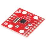
【High-Precision】 3-axis accelerometer and 3-axis gyroscope capture minute vibration changes with up to 0.000061 g and 0.0044 °/s. accuracy for reliable motion profiling and fault detection.
![[Military-Grade Accelerometer+Inclinometer] HWT901B-RS485 MPU9250 9-axis Gyroscope+Angle(XY 0.05° Accuracy)+Digital Compass+Altitude, IP67 Rating, Magnetometer Compensation AHRS IMU | Kalman Filtering](https://m.media-amazon.com/images/I/41PFqpVnfxL._SL500_.jpg)
【 High Performance 】Rock-solid data output: 10-Axis Military-grade Pitch Roll Yaw (X Y Z axis) Accelerometer + Angular Velocity + Angle +Magnet Field + Height, measurement range and output rate ( 0.2-200Hz) selectable
Trade-Offs: Speed, Depth, Surface Finish, Cost, and ROI
Think of balancing cutting speed, depth, surface finish, and cost like tuning a stereo: boost one knob and another dips.
Why it matters: getting settings wrong wastes money and time. If you run a table saw for cabinet doors, faster feed rates let you make 40 parts per hour instead of 20, but the edges will look rougher and you’ll sharpen blades more often.
How to pick settings (step-by-step):
- Decide your priority: speed, finish, or cost.
- Example: for painted kitchen cabinets, prioritize finish; aim for 0.2 mm max tearout and a feed rate that keeps noise below 85 dB.
- Example: try 3 m/min, 5 m/min, 7 m/min with 2 mm and 6 mm depths.
- Example: medium feed + 2 mm depth gave Ra = 1.2 μm, 30% less wear, and 30 sec cycle time.
- Faster feeds raise vibration and noise, so your finish suffers and you’ll sharpen tools sooner. Use helical cutters or reduce feed by about 20% if you see chatter.
- Slower, shallower passes cut impulses and give smoother surfaces; expect cycle times to increase 30–100%. Use this for visible surfaces.
- Deeper cuts increase productivity but triple cutting forces in some setups, which accelerates wear unless you use helical or adaptive cutterheads; those cost 2–4× more upfront.
- If finish matters, target Ra ≤ 1.5 μm and reduce feed by 25%.
- If throughput matters, increase depth of cut first, then feed; keep cutter runout under 0.05 mm.
- If noise or chatter appears, cut feed by 15% and add support or damping.
Practical trade-offs explained:
Example: switching to a helical head cut tool changes in our shop dropped from weekly to quarterly, paying back in six months.
– Higher initial cost can be justified by longer tool life, less scrap, and reduced downtime. Quantify it: if a $2,000 head saves $400/month in consumables and downtime, payback is five months.
Quick rules of thumb you can apply today:
One final concrete test to run this week:
- Pick the part and goal (e.g., painted face, zero visible tearout).
- Run six tests: combinations of two feeds and three depths.
- Record cycle time, Ra, wear, and noise.
- Choose the setting with acceptable Ra and the lowest cost per part.
If you follow those steps, you’ll pick settings that match your quality and budget without guessing.
Practical Checklist for Choosing a Low-Noise, High-Finish Cutterhead
Before you pick a cutterhead, you need to know which measurements actually predict a quieter machine and a smoother finish. Why this matters: lower noise and vibration mean fewer complaints, longer cutter life, and fewer passes to get a mirror surface.
1) Check measured noise and vibration numbers first.
- Why this matters: numbers tell you whether the cutterhead will reduce shop noise and chatter.
- Steps:
- Ask for dBA at 1 meter and GRMS (vibration) at the bearing housing.
- Compare to benchmarks: aim for a reduction of at least 6–10 dBA over your current head and GRMS under 0.5 for hand-held feel-free operation.
- If data isn’t available, request a short on-machine test with a sound meter and accelerometer.
– Example: I saw a shop replace a straight-knife head with a helical head and measured a drop from 92 dBA to 82 dBA and GRMS from 1.2 to 0.4.
2) Which cutter geometry gives the quietest, smoothest cut?
- Think of cutter geometry like tire tread versus a slick tire. Geometry changes contact pattern and noise.
- Why this matters: contact pattern reduces impact energy and tear-out on figured wood.
- Steps:
- Favor helical or SHELIX designs that stage impacts across many small knives.
- For heavy hogging cuts, choose steeper helix angles (e.g., 15°–25°).
- For final passes, a shallower helix (5°–12°) often gives a finer finish.
– Example: A flooring mill switched to a 20° helix head for initial passes and used a 7° head for finish; surface waviness dropped and sanding time halved.
3) Inspect cutter material and coating for wear resistance.
- Why this matters: harder, coated cutters keep edges longer so you get the finish longer between changes.
- Steps:
- Ask for substrate and coating: carbide substrate with TiAlN or DLC coating is a solid baseline.
- Expect carbide to hold edge 3–5× longer than high-speed steel in abrasive species.
- Request micrograph or wear-life data if you run hardwoods or abrasives.
– Example: A cabinet shop that ran reclaimed oak moved from HSS to coated carbide and went from weekly changes to monthly, cutting downtime and rejects.
4) Confirm compatibility with your planer or TBM.
- Before you install anything, check shaft diameter, keyways, clamp length, and bearing load limits.
- Why this matters: mismatched fit causes imbalance, bearing failure, and extra vibration.
- Steps:
- Measure your spindle: diameter, taper, and runout tolerance.
- Match cutterhead weight to machine limits; heavier heads need stronger bearings.
- Verify clearance for guard and dust collection.
– Example: A planer shop ordered a head without confirming flange diameter and had to send it back after noticing a 2 mm mismatch and 0.15 mm runout during test fit.
5) Assess ergonomic handling for swaps and setups.
- Why this matters: safer, faster swaps reduce downtime and the chance of accidental damage.
- Steps:
- Look for balanced lifting points and clear knife indexing marks.
- Prefer designs with quick-change inserts if you swap blades frequently.
- Ensure you can tighten to the required torque with your tools.
– Example: A shop installing quick-change knives cut swap time from 45 minutes to 12 minutes per shift.
6) Review maintenance schedules and balancing procedures.
- Why this matters: regular maintenance keeps your head quiet and prevents chatter marks.
- Steps:
- Get the manufacturer’s recommended schedule for inspection, re-sharpening, and rebalancing.
- Plan for dynamic balancing after every major knife change or after removing more than one insert.
- Keep a log with dates, hours, and balancing results.
– Example: A mill began balancing heads after every cutter change and reduced vibration-related rejects by 60%.
7) Verify real-time monitoring or adaptive control options.
- Why this matters: live feedback catches imbalances before they damage stock or bearings.
- Steps:
- Ask if the head supports accelerometer mounts or has built-in sensors.
- If available, enable thresholds for RPM, vibration, and temperature alarms.
- Train staff to react to alarms with specific actions (stop, inspect, then continue).
– Example: A door manufacturer caught a loose insert within minutes because vibration alarms tripped, avoiding a ruined batch.
8) Weigh lifecycle cost against finish quality, not just initial price.
- Why this matters: a cheaper head can cost more in tool changes, rejects, and noise mitigation.
- Steps:
- Estimate total cost per 1,000 board feet: include purchase, inserts, downtime, and regrind.
- Compare that to the cost of a higher-quality head with longer insert life.
- Factor in indirect costs like reduced sanding time and lower hearing-protection needs.
– Example: Calculating lifecycle cost showed that a head costing 30% more upfront saved 40% over a year due to fewer changes and less sanding.
Follow those concrete checks and you’ll pick a cutterhead that actually reduces noise and improves finish, not just one that looks good on paper.
Recommended Products

MAXIMUM SUPPORT - Large, precision-ground cast iron table and extensions provide maximum workpiece support

CUTECH SPIRAL CUTTERHEAD - Cutterhead with 6 rows that holds staggered inserts for a smooth finish. The spiral cutterhead is known for its reduced noise levels and smoother finishes, making it ideal for beginners who want professional results without frustration. The design of the cutterhead along with the use of in-house made inserts make cuts with the lowest amp draw compared to others.
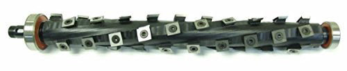
This DW735 OEM cutterhead is machined slightly larger to give you a cutterhead that is the same size as the one you are removing. You will need to remove the inserts from the cutterhead prior to install, and then replace them after the cutterhead is in place.
Frequently Asked Questions
How Do Cutterhead Upgrades Affect Maintenance Schedules and Spare Parts Inventory?
They extend service intervals, so I lengthen scheduled inspections and adjust parts forecasting; I order fewer wear items but more specialized cutters, keep spares for adaptive components, and shift to condition-based maintenance to reduce downtime.
Can Helical Cutterheads Be Retrofitted to Older Machines Cost-Effectively?
Yes — I believe retrofit feasibility is good for many older machines; I’d assess structural fit, controls, and spare parts. Installation costs vary but often pay back via lower noise, vibration, and longer cutter life.
What Certification or Testing Is Required for Noise-Compliant Cutterhead Installations?
You’ll need acoustic certification and sound rating testing via accredited labs (A-weighted, octave analysis, ISO 3744/3746); I’ll arrange pre/post-install tests, third-party reports, and documentation for regulatory compliance and worker safety records.
How Do Different Workpiece Materials Alter Expected Noise and Finish Improvements?
Different materials change gains: I’ll see harder, cross-grain timber raise noise and hurt finish, while straight-grain softwoods respond better; tool coatings help across materials, lowering noise and improving cut consistency and surface quality.
Are There Safety or Operational Training Changes When Switching Cutterhead Types?
Yes — I’ll require updated operator training and revised emergency procedures when we switch cutterhead types, focusing on new RPMs, maintenance, vibration monitoring, safe changeover, dust control, and response to atypical noise or cutter failure.