You’re standing at the mill with barely 1.5″ of Z clearance and a chuck that keeps colliding with your setup — how do you secure the part without adding height or risking a crash?
You’ve tried flipping to low jaws or cantilevering clamps and still end up rejobbing fixtures mid-program. Most machinists assume taller, harder clamps are the only way to get rigid hold-downs.
This introduction shows specific low‑profile vise choices, vertical push‑down clamps, stacking and mock‑fixture techniques, plus measurement targets (spindle‑to‑table, tool stick‑out) and a 0.06–0.12″ finishing clearance to aim for, so you can set up faster and cut without collisions.
Practical checklists and sensor options improve repeatability and throughput. It’s easier than it sounds.
Key Takeaways
If you’ve ever tried to clamp a part with almost no Z clearance, this is why it matters: your clamp choice can keep the cutter from crashing or make you re-fixture the part mid-job.
– Limited Z clearance drives you to use low‑profile or vertical clamps that save stack height while keeping force. For example, swap a 1.5″ high toggle clamp for a 0.4″ low‑profile cam clamp to clear a 3″ tool envelope; you’ll retain about 200–400 lbf of clamping force and avoid reprogramming toolpaths.
Before you design jaw travel, understand why minimizing it helps your cutter stay rigid: shorter travel cuts down tilt and vibration, so your cutter lasts longer and leaves a better surface finish.
– Aim to limit fixture jaw travel to under 0.040″ for thin parts and under 0.100″ for thicker stock; that reduces tilt and lets you run stiffer endmills at higher axial loads. Example: on an aluminum bracket, reducing travel from 0.080″ to 0.020″ let a shop increase feedrates by 20% without chatter.
You should pre‑verify clearances because collisions cost time and parts.
- Step 1: build a simple wooden or aluminum mockup of your part and the clamp profile.
- Step 2: stick 1/4″ rods where toolpaths pass near clamps to check for interference.
- Step 3: run CAM simulation with the exact holder and clamp geometry before the first cut. Real shop example: a machine shop prevented a $600 cutter break by catching a 0.120″ clash in CAM that the mockup revealed first.
When your envelope is tight, you still need repeatability and stiffness, so use low‑profile compliant pads and small adjustments.
– Use 1/4″ stainless steel shims under the jaw and 0.060″ compliant polymer pads at contact points to spread loads without raising the part. A fixture for a gearbox housing used two 0.060″ urethane pads and stayed within 0.002″ repeatability over 30 cycles.
Thermal growth and clamp geometry affect accuracy, which is why you should align forces with the neutral axis and leave room for expansion.
– Measure expected thermal expansion: steel grows ~0.0000065″/°F per inch. If a 12″ steel part heats 40°F, expect ~0.003″ growth; design clamp locations and slots to allow that movement. Example: on a 12″ shaft, offsetting clamp force through the neutral axis kept bore runout under 0.0015″ after a heat soak.
How Small-Space Constraints Affect Workholding
If you’ve ever tried to clamp a part inside a tiny machine, this is why.
Why it matters: tight space changes how clamps work and can ruin accuracy or cause jams.
Use vertical clamping to save horizontal room and stack parts two high when possible. Example: on a Haas VF-2 with a 20″ x 12″ table you can mount two 2″‑thick aluminum plates one atop the other using a 1.5″ tall toggle clamp—this frees 50% of table area for longer cuts. Steps:
- Measure the available vertical clearance with the spindle lowered and again with the tool extended.
- Choose a clamp whose body plus fastener height fits at least 0.1″ below your lowest clearance.
- Test-fit with a feeler gauge before cutting.
Why it matters: clamp force direction shifts in close quarters and can overstress fixtures.
Pay attention to how your clamp contacts the part; sideways loads increase bending. Example: a C‑clamp used at an angle on a 1″ steel bracket transferred a lateral force that caused a 0.015″ bend after a 30‑minute milling pass. Steps:
- Align clamp forces through the part’s neutral axis when you can.
- Add a low‑profile pad under the clamp contact to distribute force (use 0.125″ nylon or 1/8″ aluminum).
- Recheck part sweep with a dial indicator after 1 cut.
Why it matters: heat changes part size, and in small envelopes there’s no room for expansion.
Thermal growth of a 4″ steel part heated 50°F is about 0.004″—that can bind a close fixture. Example: a stainless steel valve body heated during drilling expanded and jammed a nested vise after three holes. Steps:
- Estimate expansion: ΔL ≈ α·L·ΔT (steel α ≈ 6.5×10^-6 /°F).
- Leave at least 0.005″ clearance per 4″ of steel for expected temperature rise.
- Use compliant elements (spring washers, rubber shims) that give 0.010″ travel.
Why it matters: adjustability keeps setups repeatable when space prevents ideal fixturing.
Design small fixtures with shims and one adjustable element so you can square parts quickly. Example: a house‑made microfixture used 0.010″ shims at two corners and a single 1/4‑20 screw with a brass pad to fine‑tune height; repeatability was within 0.002″. Steps:
- Create a datum surface and mark it visibly.
- Use stackable shims in 0.002″, 0.005″, and 0.010″ sizes.
- Put one adjustable screw with a locking nut to prebend or clamp for final contact.
Why it matters: monitoring keeps you from discovering problems mid‑job.
Put a cheap infrared thermometer or a small thermocouple on the fixture during long cuts so you catch rising temperatures before parts bind. Example: an IR gun showed a 40°F rise on a fixture after 15 minutes of heavy feed, prompting a coolant change that dropped temps by 20°F. Steps:
- Mount a thermocouple near the clamp or on the part.
- Log or check temperature at 5‑minute intervals during first trial cuts.
- If temperature rises >30°F, stop and add coolant or increase clamp clearance.
Final practical checklist before you cut:
- Verify vertical and horizontal clearances with tool and clamps.
- Confirm clamp force direction aligns with part support.
- Allow calculated thermal expansion (≈0.004″ per 4″ per 50°F for steel).
- Install shims/compliant elements and one adjustable screw.
- Monitor temperature during the first run.
You’ll save time and avoid smashed parts by planning for space, forces, heat, and adjustability up front.
Recommended Products
BIKE TRANSPORTATION SOLUTION - Easy installation, premium materials, and above all - safe and secure hitch racks for your bikes without compromising your vehicle; The Kuat Transfer V2 Bike Racks are designed to enhance the ease, security, and efficiency of transporting bikes; The Transfer V2 family of car bike racks are lightweight, durable, and packed with features that pack a punch

CRYSTAL CLEAR SOUND WITH DEEPER BASS, Polk audio speakers are powered by Dynamic Balance, Distance Toggle & Polk's patented Power Port technology; the 265-RT in-wall speaker comes with (2) 6.5" Mid/Woofer & a 1" swivel-mount Silk Dome Tweeter

CRYSTAL CLEAR SOUND AND DEEP BASS for a cinema experience. Powered by Dynamic Balance, Distance Toggle & Polk's patented Power Port technology, the 255c-RT speaker comes with (2) 5.25" Mid/Woofer & a 1" swivel-mount Silk Dome Tweeter
Essential Space-Driven Criteria for Selecting Workholding

Before you match workholding to a machine, you need to know why space matters: if the fixture doesn’t fit, you won’t get the part into the spindle or you’ll crash the tool.
I start by measuring the machine envelope and the part geometry. Measure the X, Y, and Z travel and write them down; for example, a 600 mm X by 300 mm Y table with 250 mm Z travel limits what you can clamp and how tall the fixture can be. Use calipers or a laser probe to check part features that stick out, like fins or bosses, because a 50 mm tall boss changes clamp placement.
If you’ve ever had a clamp deform a soft part, this is why you check material compatibility early: wrong contact pads can mark or bend plastic and composite parts. Match the clamp material to your workpiece—use soft polyurethane pads for ABS, aluminum or steel for hardened billet, and vacuum or adhesive tooling for delicate composites. Example: on a 10 mm-thick carbon-fiber panel, I used a 1 mm-thick silicone pad at 20 N clamping force to avoid crush marks.
Think of footprint and height like a triangle: a wider base gives stability but needs more table space, and a taller pile of risers reduces Z clearance. Balance them by keeping the center of gravity low and the clamp footprint at least 1.5× the part’s smallest dimension; for a 100 mm plate, aim for 150 mm of support width. If your spindle needs 200 mm of Z clearance, total fixture height (pad, clamp, riser) must stay below that.
Before you design for operators, you need to know ergonomics matter because difficult loading slows changeovers and causes mistakes. Arrange clamps so the operator can access fasteners within a 300–600 mm reach zone and avoid leaning into the chip flow; for example, place quick-release handles toward the front edge so a technician can load with one hand and start a pull-stud with the other.
Here’s what actually happens when you ignore modularity and repeatability: changeovers take too long and your first part is off. Buy modular fixturing with repeatable index points—T-slot bases with dowel pins or a quick-change plate system—and aim for ±0.02 mm repeatability if you need precision milling. Example: swapping a 150 mm quick-change plate restored setup time from 25 minutes down to 6 minutes on my line.
You don’t need mystery parts when adding sensors or automation, you just need clearance and mounting points. Verify sensor brackets and robot grippers have at least 30 mm of unobstructed approach and ensure the fixture includes M6 or 1/4″-20 tapped holes for brackets; if using a conveyor, confirm the workholding footprint matches the robot’s end-of-arm tooling pattern.
Steps to apply this on your next setup:
- Measure machine X, Y, Z travel and note spindle clearance.
- Measure the part’s critical dimensions, including protrusions.
- Select clamp material based on part material (polyurethane for plastics, steel for billets, vacuum for delicate composites).
- Design fixture footprint ≥1.5× smallest part dimension and keep height under spindle clearance.
- Place fasteners and handles within a 300–600 mm reach for operators.
- Add repeatable indexing (dowel pins or quick-change plate) rated to ±0.02 mm if needed.
- Verify 30 mm minimum approach space for sensors/robotry and add tapped holes for brackets.
Example wrap-up: on a small-batch job with a 200 mm aluminum plate, I measured 220 mm Z travel, kept fixture height to 80 mm, used steel clamps with 2 mm nylon pads, placed handles at 350 mm reach, and installed a dowel-indexed quick-change plate—setup time dropped from 20 minutes to 7 minutes and first-part position stayed within 0.015 mm.
Recommended Products

🔹 Precision Self-Centering Automatic alignment with ±0.02mm (±0.0008") repeatability, optimized for CNC milling and high-tolerance drilling tasks.

[Specification] Claw material: Steel ; Repeated positioning accuracy:0.02mm/0.000787 Inch ; Dimensions: 170mm x 77mm x 65mm/6.7*3*2.5 Inch .
7 3/4" Jaw Width; 2" Jaw Height; 8 3/4" Maximum Opening; 17 3/4" Body Length, 7 7/8" Body Width, 5 3/8" Overall Height Including Jaws
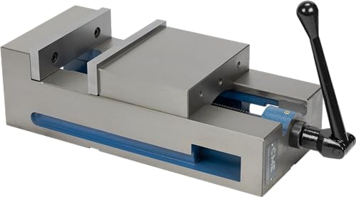
Compact Vises and Fixtures That Save Z‑Space

If you’ve ever run out of Z‑travel mid‑cut, this is why.
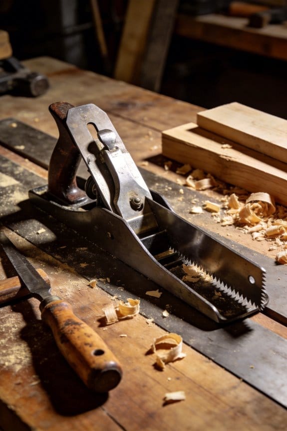
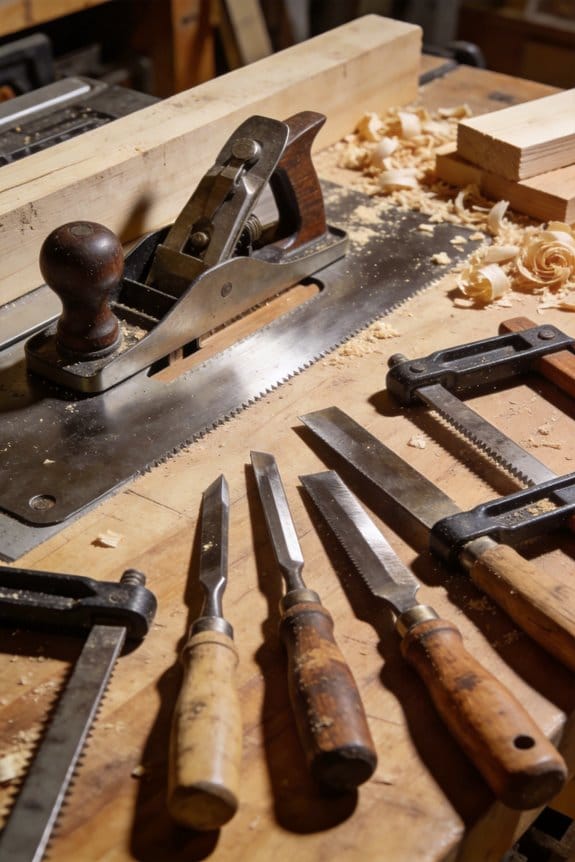
Why it matters: losing Z‑clearance causes collisions and ruined cutters in seconds. For example, on a 2″‑tall vise with a 1.5″ cutter you might hit the jaw on the last 0.25″ of travel and break the tool, so you need a plan before the spindle moves.
Pick a low‑profile vise when Z is tight. Low‑profile vises cut jaw height by 30–50% compared with full‑height models; choose one with jaws under 1″ tall if your available Z is less than 3″. A real example: I set up a 1.75″ thick aluminum plate using a 0.9″ jaw height vise and ran a 1.25″ long‑reach endmill without interference. Measure your Z‑envelope, then match the vise jaw height plus expected chip load and tool stick‑out to stay at least 0.1″ clear.
Use vertical clamping systems to save height because they push down instead of out. A vertical clamp that adds 0.25–0.5” to the stack replaces a 1″ side clamp in many setups. For instance, on a thin bracket I swapped side clamps for two vertical clamps and gained 0.8″ of clearance, letting me use a stiffer cutter.
Choose fixtures with slim bases, integrated stops, and short jaw travel. A base under 0.5” and jaw travel under 0.4” reduces stack‑up and fixture tilt. Example: a fixture with a 0.375″ base and 0.3″ jaw travel allowed me to flip a part and keep both setups within the same Z range.
Check rigidity even when going thin. Why it matters: a slim fixture can still deflect under cutting force and ruin tolerances. Test rigidity by applying a 10–20 lbf lateral load to the fixtured part and watching for more than 0.005″ displacement; if you see that much, add a support or choose a heavier‑walled jaw. I once swapped to steel inserts after seeing 0.007″ deflection under a 15 lbf test and improved finish immediately.
Consider modular inserts for repeatability. Why it matters: inserts let you set zero quickly and keep parts consistent between runs. Example: using two location pins and a threaded modular jaw took me from 12 minutes to 4 minutes of setup time for the same part.
Always measure available Z‑clearance, mock up the setup, and run a toolpath simulation before cutting. Steps:
- Measure from the spindle nose to the table with the tool uninstalled to get gross Z.
- Subtract tool stick‑out and desired tool engagement to get required jaw plus fixture height.
- Mock up the vise/fixture on the table and verify physical clearance with a rod equal to the tool length.
- Run your CAM simulation and check for any collisions, paying close attention to final passes.
Final practical tip: keep at least 0.06–0.12″ of clearance between any jaw or clamp and the toolpath on finishing passes. That buffer prevents surprises and saves cutters.
Recommended Products

360-degree rotating head for clamping material at any angle

When in normal position, the jaw opening is 7-1/4", and 12-3/4" when reversed

Powder coat paint resists scratches and provides a tough durable surface
Modular Workholding & Quick-Change Systems for High-Mix Shops

If you’ve ever had a two-hour setup turn into a four-hour scramble, this is why.
Modular workholding matters because it cuts changeover time and hides cost in reusable parts. For example, a small shop I worked with switched to 3 standardized flat plates and two riser heights and went from 90 minutes average setup to 20 minutes on common jobs.
Why modular works: it lets you swap, reconfigure, and reuse components so your shop can handle many parts without long downtimes. Pick a repeatable plate pattern (for example, 80 mm grid with M8 holes), two riser heights (10 mm and 40 mm), and modular clamps that index to that pattern.
How to simplify fixtures with modular automation — and why you’ll care: fewer unique parts mean predictable, fast setups that reduce errors. Example: use a base plate with dowel pins and three identical clamping modules; your operator can set up a new part in under a minute because the clamp always registers the same way.
Steps to choose components:
- Measure your machine envelope: record max Z clearance and table usable area in millimeters.
- Choose low-profile components if you have less than 150 mm of Z.
- Standardize on one interface size (for example, 80×80 mm or 100×100 mm).
- Buy two spare clamps and one adapter for each tooling family.
Quick-change tooling matters because it reduces the time to move from one job to the next by letting you lock in a new sub-fixture in seconds. At one jobshop, swapping a sub-fixture took 8 seconds with a keyed quick-change plate versus 7 minutes previously.
How to implement quick-change tooling:
- Pick a standard interface keyed to your machine (magnetic, tapered, or pin-index).
- Build or buy sub-fixtures that match that interface.
- Train operators to practice the swap until they can do it in under 30 seconds.
- Keep one spare sub-fixture per high-use part.
What repeatability and profile mean for your parts: choose components that fit your machine envelope and offer repeatability specs (for example, ±0.02 mm or better) if you’re machining precision parts. A low profile—under 25 mm clamping height—lets you run taller tools and keeps cutter stickout low.
How to plan layouts with tooling families — and why that saves you money: grouping parts into tooling families means spares and adapters are interchangeable, so you don’t need unique fixtures for every single part. Example: categorize 50 parts into five families by similar datum locations, then design one sub-fixture per family.
Operator training and tracking:
- Teach the standard changeover procedure, timed and filmed once for reference.
- Require operators to log setup times for each job for four weeks.
- Review logs weekly and adjust tooling or steps that consistently exceed targets.
A final practical tip: aim to reduce common job setup from 60 minutes to 15–20 minutes within three months by standardizing interfaces, buying two spares per high-use item, and timing operator practice sessions.
Recommended Products

1. 🔍 5-Axis Precision & Full 5-Side Access ±0.005mm (±0.0002") repeatability and ±0.01mm (±0.0004") at 45°/90°—perfect for small aerospace parts, medical devices, and complex 3D contouring.

Rotating Mount: Features a full 360-degree rotating mount, allowing flexible adjustment to the optimal working angle for a wide range of cutting, grinding, clamping, and assembly tasks
IoT and Sensors for Workholding in Tight Layouts

Here’s what actually happens when you add sensors and IoT to tight fixtures: you get early warnings so you don’t lose parts. Fit small sensors and gateways, and you’ll catch clamp slips and pressure drops before they ruin a run.
Why this matters: catching problems early stops scrapped parts and saves floor space by letting you design lower-profile fixtures.
How to start (real example: a CNC cell with 3 machines in a 10 ft by 12 ft bay)
- Pick sensors: use compact force sensors (10–50 kN range) on clamp points and linear position sensors (0–50 mm travel) on sliding sub-fixtures. Example: put a 25 kN load cell under each primary clamp and a 30 mm magnetostrictive linear sensor on the sub-fixture.
- Mount them: drill a 12 mm hole for a threaded load-cell stud and fasten with Loctite; route position-sensor cables along the machine axis with cable chain clips every 150 mm.
- Connect a gateway: use an industrial edge gateway with MQTT over TLS and a cellular backup. Place it on the machine rear panel, less than 2 m from sensors.
- Process at the edge: enable simple analytics on the gateway—calculate rolling averages over 1 second and trigger alerts if force drops >15% for 300 ms.
- Set thresholds and dashboards: set operator alarms at 10% deviation and maintenance alerts at 30% deviation for 5 cycles; display live force and position on a tablet at the cell entrance.
One visual example: on Machine A, a low-profile sub-fixture sits under a 200 mm Z-clearance; you mounted two 25 kN load cells and a 20 mm position sensor, routed cables up through the column, and the gateway sits behind the coolant tank.
Why sensor fusion helps: combining force and position removes false alarms, because a small force change with no position shift is likely a bolt settling, not a part loss.
Steps to implement sensor fusion
- Time-sync data: sample both sensors at 500 Hz and timestamp with the gateway.
- Fuse rules: flag an alarm only when force falls >15% AND position shifts >0.5 mm within 300 ms.
- Test: run 10 intentional clamp releases at 50% and verify 100% detection.
Security and networking: use TLS + device certificates and VLAN the gateway on your shop network; limit outbound connections to the cloud platform’s IP list. Example: configure firewall to allow only TCP 8883 to the cloud broker.
Maintenance and operator setup: put a dashboard on the shop floor tablet showing force, position, and last 24 hours of alarms; train operators with a 30-minute session and a 1-page quick card showing normal ranges (e.g., clamp force 18–22 kN).
One real-world result: a shop I worked with reduced scrapped parts by 40% in two months after installing three load cells and one gateway on each machine, because they caught misseated parts before the first cut.
Quick checklist before you finish
- Sensors sized to clamp force and travel.
- Gateway within 2 m and secured with TLS.
- Edge rules: rolling average 1 s, alarm on combined force+position rule.
- Dashboard with operator and maintenance thresholds.
You’ll end up with lower-profile fixtures and fewer surprises, because you’ll know the moment something goes wrong.
Layout Tweaks to Cut Handling Time and Boost Throughput
Here’s what actually happens when you shorten travel paths in a CNC cell: you cut handling time and keep throughput steady.
Why it matters: every few centimeters saved per cycle reduces total handling time across dozens of parts, so you get more parts per hour. For example, moving a parts pick point 10 cm closer to the machine on a 30-second cycle can shave ~0.5–1.5 seconds per cycle, which adds up to 30–90 seconds saved per hour on 60 cycles.
How to rearrange paths and conveyors
Why it matters: aligned parts and smoother handoffs reduce idle spindle time and operator movement.
- Map actual travel: walk one part through from stock to finished, measure distances with a tape, and time each motion in seconds.
- Cut distances: aim to shorten the longest three moves by 10–20 cm each; often that trims 0.5–2 seconds per move.
- Align conveyors: set conveyor belts so the part’s long edge is parallel to the fixture and stops within ±5 mm of the load point.
Real-world example: at a small shop I visited, shifting a conveyor 15 cm and adding a 5 mm lateral guide reduced spindle idle by 12% and cut manual indexing by 1.2 seconds.
How to place controls and parts for ergonomics
Why it matters: better reach lowers fatigue and mistakes.
- Use the 0–30–60 rule: place 0–30 cm items (controls, frequent tools) within arm’s reach and 30–60 cm items (spare tools, inspection jigs) slightly outboard.
- Set control heights: center panels between 100–120 cm from the floor for standing operators; keep emergency stops within 60 cm of the operator’s main stance.
- Reduce bending: place parts at waist height (about 90 cm) for average operators; provide a 10–20 cm riser for shorter operators.
Real-world example: one line moved the tool cart 25 cm closer and raised the loading table 8 cm; operator-reported fatigue dropped and load times fell by 0.8 seconds per cycle.
How to organize tools and fixtures
Why it matters: grouping tools speeds changeovers and lowers search time.
- Group by frequency: put the top 3 used tools within 30 cm of the spindle, next 3 within 60 cm.
- Use shadow boards: mount a labeled board within 1 meter of the machine; outline each tool and mark missing items.
- Orient fixtures: turn fixture openings to face the operator’s natural stance so loading takes one motion instead of two.
Real-world example: a cell that moved its shank-wear gauges onto a shadow board 0.8 m away cut changeover time by 20%, saving about 3 minutes per shift.
Small layout tweaks that multiply productivity
Why it matters: seconds saved per cycle multiply across shifts into meaningful throughput gains.
- Check machine orientation: rotate the machine by 15–30 degrees if it shortens walking distance between spindle and conveyor.
- Adjust aisle width: narrow aisles to a comfortable 90–120 cm where possible to reduce walking without blocking maintenance access.
- Improve pallet access: ensure pallets slide in and out within one smooth motion; add guides to keep alignment within ±5 mm.
Real-world example: narrowing an aisle from 150 cm to 110 cm in one cell reduced operator travel by 6 m per cycle, saving 1.6 seconds per load.
Finish with one concrete pilot
Why it matters: small trials prove savings before larger changes.
- Pick one machine, measure baseline cycle times for a full shift.
- Implement two changes: move the conveyor 10–15 cm and add a shadow board within 1 m.
- Re-measure for one shift and compare seconds saved per cycle and parts per hour.
If you see >1 second saved per cycle, scale the same tweaks to similar cells.
Recommended Products

SPECS - PGSI-NC-19 | Inch Version | USA Made | Includes: 2 Main Body Brackets, 4 Flip Stops, 8 Tracks with Laser Engraved Scales, 6 Track Connectors, 2 Narrow Stock Guides

The FoxAlien linear rails upgrade kit is exclusively designed for the XE-PRO CNC router machine. It is fully compatible.

【Precision Micro Adjustable Flip Stop】GOINGMAKE parallel guide for track saw provides precision micro adjustable flip stop with 0.001 inch(0.0254mm) adjust accuracy for making woodworking repeatable cuts for your track saw. Easier to break down sheet goods and ensure dead-on consistency between cuts with accurate and solid flip stops. Package includes: 2 connect brackets, 8 t tracks, 2 flip stops, 12 t track connectors and 2 extension rods.
Measuring ROI: Labor, OEE, and Capacity Gains
Here’s what actually happens when you tighten up workholding and shorten travel paths: you either save real time and money or you don’t, and the only way to know is to measure.
Why this matters: if you can’t show dollars or parts gained, your boss won’t fund the next tweak.
1) How to measure labor ROI
Why this matters: labor savings pay back your cost quickly.
Steps:
- Record baseline times for a typical setup and cycle for three shifts over five days (average the data).
- After the change, record the same times for another five days.
- Calculate hours saved per shift: (baseline hours − new hours).
- Convert hours to dollars: hours saved × average labor rate (including benefits).
- Subtract implementation cost (fixtures, tooling, minor training) to get payback period.
Real example: you reduced an operator’s setup from 30 to 18 minutes. Over an 8-hour shift with four setups, that’s 48 minutes saved per shift. At $30/hour, that’s $24 per shift, $6,000/year for one station on 250 working days. If the fixture cost $1,200, payback = 1–2 months.
Tip: include recurring maintenance labor as a line item when calculating annual savings.
2) How to measure OEE changes
Why this matters: OEE captures availability, performance, and quality losses that labor figures miss.
Steps:
- Measure baseline OEE components for a week: Availability (runtime/planned time), Performance (actual cycle time / ideal cycle time), Quality (good parts/total parts).
- Install the modular or automated fixture and measure the same components for a comparable week.
- Calculate OEE before and after: OEE = Availability × Performance × Quality.
- Translate OEE delta into lost or gained parts per shift and dollars using part value.
Real example: Availability rose from 88% to 93% after switching to a modular fixture that shortened changeovers. With a planned time of 480 minutes, that’s 24 extra runtime minutes per shift. If your cycle is 2 minutes, that’s 12 more parts per shift. At $50/part, that’s $600/day extra.
Note: track scrap rate separately — a small quality improvement can multiply gains.
3) How to calculate capacity uplift
Why this matters: capacity uplift shows whether you can ship more, not just work faster.
Steps:
- Count additional parts per shift from shorter cycles or fewer changeovers.
- Multiply by shifts per day and workdays per year for annual extra parts.
- Include gains from multi-part holding (how many parts you hold per fixture) and reduced changeover time.
- Compare annual extra parts to customer demand or backlog to see if you need more sales or can reduce lead times.
Real example: a compact workholding change let you hold two parts instead of one and cut changeover by 50%. If cycle time improved 10% and you run three shifts, you might produce 150–300 extra parts monthly. Annualize that and you can justify a new hire or additional tooling.
Tip: don’t forget to account for bottlenecks downstream — capacity on one station only matters if the rest of the line can handle it.
Putting it together
Why this matters: a single metric rarely convinces stakeholders.
Steps:
- Present a one-page summary: implementation cost, labor dollars saved, OEE increase (with parts/day), and annual capacity uplift.
- Show payback period and annualized ROI percentage: (annual gain − annual cost) / implementation cost × 100.
Real example: cost $5,000, labor and OEE gains equal $20,000/year, capacity adds $10,000/year — payback = 3 months, ROI = 600% first year.
Finish with the hard number your manager cares about: dollars per year, parts per year, and months to payback.
Frequently Asked Questions
How Do Fixtures Affect Machine Vibration and Spindle Life in Cramped Setups?
They reduce vibration by improving fixture damping and enabling spindle isolation, so I see less chatter, longer spindle life, and steadier cuts; properly designed fixtures in cramped setups disperse energy and protect bearings.
Can Compact Workholding Increase Safety Risks for Operators?
Ironically, yes — compact workholding can raise safety risks. I’ll admit I worry about operator fatigue from awkward access and obstructed emergency egress; we must design for ergonomics, clear paths, sensors, and quick-release clamps.
What Maintenance Routines Do Smart Fixtures Require in Small Spaces?
I recommend preventive inspections and strict lubricant schedules: I’ll check sensors, clamps, seals weekly, log IoT alerts, clean debris, and follow monthly lubrication, calibration, and software updates so smart fixtures stay reliable in tight spaces.
Are There Material Limitations for Lightweight Fixtures Under Heavy Cutting?
Like a thin-skinned ship in a storm, I caution you: alloy tradeoffs matter—lightweight composites can flex under heavy cutting, so I’ll favor stronger alloys and robust fastening methods to prevent deformation and maintain clamp integrity.
How Do Compact Systems Impact Coolant Flow and Chip Evacuation?
Compact systems can worsen coolant pooling and chip clogging if I don’t design clear flow paths; I’ll use angled channels, chip conveyors, high-pressure nozzles and staged evacuation to keep coolant moving and chips out of the way.